


228 Fieldbus Communication
WAGO-I/O-SYSTEM 750
750-882 Media Redundancy ETHERNET Controller
Manual
1.5.0
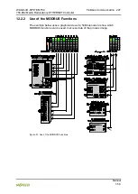
Use register functions to access analog signals and coil functions to
access binary signals!
It is recommended that analog data be accessed with register functions
and
digital data with coil functions
. If reading or writing access to binary signals is
performed via register functions
, an address shift may occur as soon as further
analog modules are operated on the coupler/controller.
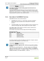
12.2.3 Description of the MODBUS Functions
All MODBUS functions are executed as follows:
1.
A MODBUS TCP master (e.g., a PC) makes a request to the WAGO
fieldbus node using a specific function code based on the desired
operation..
2.
The WAGO fieldbus node receives the datagram and then responds to the
master with the proper data, which is based on the master’s request.
If the WAGO fieldbus node receives an incorrect request, it sends an error
datagram (Exception) to the master.
The exception code contained in the exception has the following meaning:
Table 88: Exception Codes
Exception code Meaning
0x01
Illegal function
0x02
Illegal data address
0x03
Illegal data value
0x04
Slave device failure
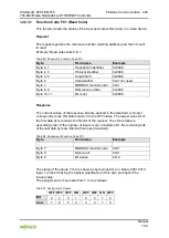
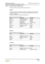
The following chapters describe the datagram architecture of request, response
and exception with examples for each function code.
Reading and writing of outputs via FC1 to FC4 is also possible by adding
an offset!
In the case of the read functions (FC1 ... FC4) the outputs can be additionally
written and read back by adding an offset of 200hex (0x0200) to the MODBUS
addresses in the range of [0
hex
... FF
hex
] and an offset of 1000
hex
(0x01000) to the
MODBUS addresses in the range of [6000
hex
... 62FC
hex
].