background image

VIPER user manual V1.0 

31 


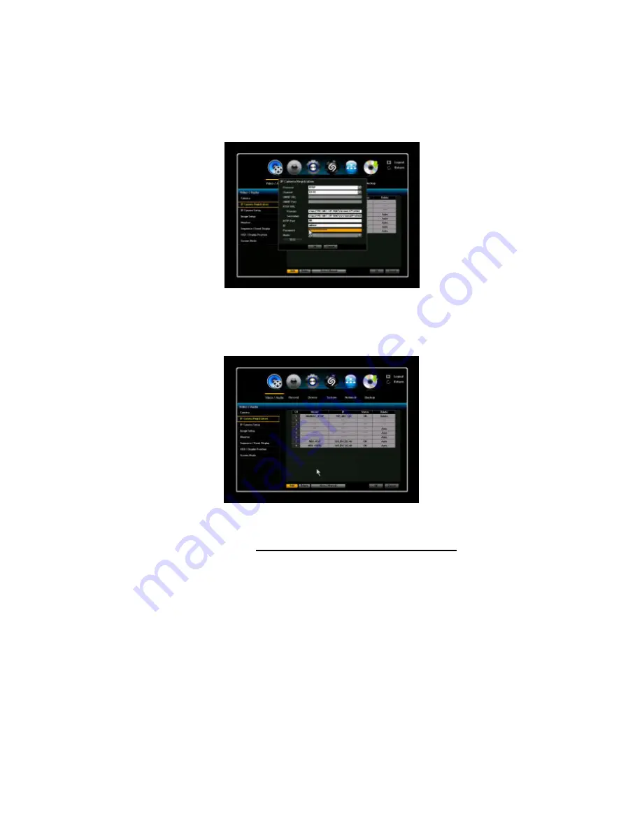
3.  Enter the correct information on the “RTSP URL”, “HTTP port”, “ID”, and “Password”. 

If Secondary stream is registered both Primary and Secondary stream are supported.    If not 

only Primary stream is supported. Click “OK” to save the configurations and then “Cancel” to 

exit the menu. 


4.  The model name of rtsp stream channel is displayed as “MANUAL_RTSP”. 


5.  For the RTSP channel added manually, only resolution information is displayed.     

IP camera image setup and 

motion/sensor event, PTZ is not supported

.     


Summary of Contents for Viper series

Page 1: ...Please read this manual thoroughly before use and keep it handy for future reference INSTRUCTION MANUAL Real Time Full HD PoE Network Video Recorders 4 8 16CH ...

Page 2: ... have it checked by the qualified personnel before operating it any further Unplug the unit from the wall outlet if it is not going to be used for several days or more To disconnect the cord pull it out by the plug Never pull the cord itself Allow adequate air circulation to prevent internal heat build up Do not place the unit on surfaces rugs blankets etc or near materials curtains draperies that...

Page 3: ...ser manual V1 0 3 CE COMPLIANCE STATEMENT WARNING This is a Class A product In a domestic environment this product may cause radio interference in which case the user may be required to take adequate measures ...

Page 4: ...s convenience receptacles and the point where they exit from the apparatus 11 Only use attachments accessories specified by the manufacturer 12 Use only with the cart stand tripod bracket or table specified by the manufacturer or sold with the apparatus When a cart is used use caution when moving the cart apparatus combination to avoid injury from tip over 13 Unplug this apparatus during lightning...

Page 5: ...ng of ONVIF cameras 28 3 1 2 4 Manual adding of cameras RTSP streams 30 3 1 3 IP Camera Setup 32 3 1 4 Image Setup Vista VK2 cameras only 33 3 1 5 Monitor 34 3 1 6 Sequence Event Display 34 3 1 7 OSD Display Position 35 3 1 8 Screen Mode 35 3 2 Record Setup 36 3 2 1 Policy 36 3 2 2 Record Quality 37 3 2 3 Record Method 37 3 2 4 Record Option 38 3 2 5 Schedule Setup 39 3 2 6 Holiday 39 3 2 7 Motion...

Page 6: ...FF 73 5 1 3 General Menu Freeze 73 5 1 4 General Menu Stop Alarm 74 5 1 5 General Menu Record Start Stop 74 5 1 6 General Menu Play 75 5 1 7 General Menu Search 75 5 1 8 General Menu Backup plus back up procedure 76 5 1 9 General Menu Main Menu 79 5 1 10 General Menu Information 80 5 1 11 General Menu IP Cam INFO 80 5 1 12 General Menu Easy Setup 81 5 1 13 General Menu IP Camera Registration 81 5 ...

Page 7: ...on 102 9 1 2 6 Record Option 103 9 1 3 Device 103 9 1 3 1 Sensor Detection 103 9 1 3 2 Video Loss Detection 103 9 1 3 3 Alarm Out Schedule 104 9 1 3 4 PTZ 104 9 1 3 5 System Controller Printer Device 104 9 1 3 6 Storage 105 9 1 4 System 106 9 1 4 1 Date Time 106 9 1 4 2 Time Synchronization Setup 106 9 1 4 3 Signal Language Device name 106 9 1 4 4 Config 107 9 1 4 5 System Information 107 9 1 4 6 ...

Page 8: ...VIPER user manual V1 0 8 TERMS ICONS GLOSSARY 125 NVR Icon Reference 126 ...

Page 9: ...Note Check your package to make sure that you received the complete system including all components shown above 1 3 Key Features The NVR is the most competitive device developed for all industrial applications It supports real time and crystal clear picture quality with small recording file size and powerful remote control function Major features include Real time live real time recording 4 8 16 c...

Page 10: ...easy installation of multiple NVRs Control of minimum recording dates by channel Mobile I Phone Android phone support Video Analysis support 1 4 Basic Security System Configuration The configuration above is based on 4ch NVR Power Switch Client Software Web browser Web viewer External HDD VGA Monitor HDMI Monitor Amplified Speaker Sensor input Alarm out DC Power Adapter USB data backup USB keyboar...

Page 11: ...OTE CONTROL SENSOR Receives all incoming signals from the remote control 6 USB 2 0 Port Connect USB mouse or USB memory device for firmware upgrade 1 6 Rear Panel View VIPER04 VIPER08 VIPER16 1 IP PoE camera inputs 5 eSATA 9 USB 2 0 2 Network port 6 HDMI 10 Power input 3 Audio out 7 USB 3 0 11 Power switch 4 VGA out 8 Sensor Alarm I O 5 11 1 2 3 4 6 7 8 9 10 5 11 1 2 3 4 6 7 8 9 10 2 5 10 1 9 3 4 ...

Page 12: ... Remote Control Installing batteries 1 Remove the battery cover by sliding in the direction of the arrow 2 Insert two AAA batteries according to directions provided 3 Replace the battery cover by sliding in the direction of the arrow ...

Page 13: ...nting plate into the NVR and fix it with screws Step 5 Attach the data and power cable to HDD s correctly Step 6 Replace the top cover of NVR and fix it with screws After HDD installation Step 7 Turn the NVR power ON Step 8 NVR will detect HDD s during the booting and will format HDD s Step 9 After HDD formatting NVR will be automatically rebooted and will be ready to work with HDD s 2 2 Network C...

Page 14: ...ctions in next section to configure your router correctly If your Broadband Modem does not support internal loop back port forwarding function and you want to monitor NVR using a PC located in same Intranet you should use Direct IP instead of DVRNS in the connection menu of NetViewer If your PC is located outside of Intranet you can use both DVRNS and Direct IP to connect to NVR even though your B...

Page 15: ...0 steps will appear If you don t want to use the Easy set up simply click the Exit button Then the system will exit to main live screen However you can setup the system at anytime you want by click the Easy Setup Menu in the right click mouse menu 1 10 System Admin 2 10 Connection Mode setup The user can set the Network and IP camera connection mode required e g Static DHCP etc For detailed inform...

Page 16: ... Test 4 10 DVRNS Dashboard 5 10 IP Camera Registration The user can check the IP camera listing and register the desired IP cameras automatically or manually by click the Auto Manual button See Section 3 1 2 for more details on camera registration ...

Page 17: ...VIPER user manual V1 0 17 6 10 IP Camera Setup 7 10 Date Time Setup In this step the user can set the date and time of the system and Time zone as well 8 10 Camera ...

Page 18: ...ompleted or exited from Easy Setup menu a live screen will appear When the user is not logged in and they try to access it it will prompt you to login Enter ID and Password by using the virtual keyboard and click OK By default the ID is set at admin and the Password is set at admin ...

Page 19: ... enter up to 8 characters max If four Screen Mode Select how you would like to view screen Audio Off Select the audio on or off Freeze Freeze Playback or Live scene Stop Alarm Stops the alarm output and the event monitoring Record Start Starts stops the manual recording Play Plays the search result for 30sec 1min 5min 10min and all Search Search for recorded data by time event capture etc Backup B...

Page 20: ...characters will show as 123 and eight character 1234 2 3 4 Live Menu navigating You can navigate the screen using the mouse and remote control By selecting arrow button using mouse or pressing the direction button and enter button on the remote control you can move to the next channels ...

Page 21: ...Main Menu Tree VIDEO AUDIO RECORD DEVICE Camera Policy Storage IP Camera Registration Record Quality Sensor Video Loss Detection IP Camera Setup Record Method Alarm Schedule Image Setup Record Option PTZ Monitor Schedule System controller Printer Device Sequence Event Display Holiday POS ATM Device OSD Display Position Motion Video Analysis Screen Mode Event Record Duration SYSTEM NETWORK BACKUP D...

Page 22: ...title will be displayed on the screen COVERT 1 Video pictures will not appear and will be blank black but icons and camera title will appear Despite being in covert the NVR will continue to record COVERT 2 In this mode the screen will be completely blank including icon camera names etc but will continue to record 2 AUDIO You may select the audio ON or OFF position If you want to activate the Audio...

Page 23: ... and Password of admin This is the default settings for the VK2 range 2 NVR Search and manual registration This method can be used for cameras Including VK2 range that are connected via a switch to the WAN port on the rear of the NVR and for cameras that do not support zero config but are connected to the in built PoE switch 3 Manual adding of ONVIF cameras This method can be used to try and conne...

Page 24: ... port numbers relate to the screen segments on the 16 way split screen display 1 top left 16 bottom right Power up the NVR it will take a minute or so to boot up then will automatically detect the connected cameras and apply IP address using DHCP Wait for a short while icons showing a camera and rotating blue dots will be displayed in screen segments relating to port positions on which cameras hav...

Page 25: ...urned off for the relevant channels To do this got to Main Menu Audio Video IP Camera Registration The following screen will be displayed Click on the Auto Manual button the following screen will appear Any channel with a tick in the box is set to Auto Detection click on the box to remove the tick for the channels that require a manual set up then click on OK Next click on the Add button in the bo...

Page 26: ...button is pressed the NVR will search the network for other cameras and try to interrogate their ID and Password If the Quick box is ticked then the NVR will only search for the cameras identity and IP address Once the search is completed the list will appear as below cameras which have not been allocated to the NVR will have the word Registration displayed in the Right hand Registration column To...

Page 27: ... Password If a Detailed search has been run then the cameras ID and Password will automatically be filled in on screen so simply select the required channel number Next click on the TEST button If the camera details are correct then Success will be displayed next click OK If the camera details are wrong then Fail will be displayed Check the ID and Password details If these are correct and the mess...

Page 28: ...meras must be ONVIF version S or above To use this method the Auto Detection for that channel must be switched to off as described in the previous section Click on the Add button the registration menu will appear Click on the Manual Add button to display the following Select the required channel The address box will display the following string http 192 168 0 1 onvif device_service ...

Page 29: ...ss of required camera Next add the camera ID and Password Click on TEST if the details are correct and the camera is compatible then the message Success will be displayed Next click OK to add the camera If the message Fail is displayed double check the ID and Password if these are correct then the camera and NVR are not compatible A different camera will need to be used ...

Page 30: ...The RTSP URL for each of the cameras streams will bee required for this method A useful tool for accessing this sort of information from a camera is the ONVIF Device Managers ODM FOC software available on the web To use this method the Auto Detection for that channel must be switched to off as described in the previous section Click on the Add button the registration menu will appear 1 IP camera r...

Page 31: ...Secondary stream are supported If not only Primary stream is supported Click OK to save the configurations and then Cancel to exit the menu 4 The model name of rtsp stream channel is displayed as MANUAL_RTSP 5 For the RTSP channel added manually only resolution information is displayed IP camera image setup and motion sensor event PTZ is not supported ...

Page 32: ... by the camera Once the Resolution tab is clicked a window will appear in the middle of the page Scroll down on the Resolution bar and select desired resolution setting 3 FPS To select desired FPS click on the FPS bar and scroll down Maximum FPS allowed is 30 The NVR does not support FPS 60 4 Quality For desired quality setting click on the bar next to Quality Once the bar has been clicked a virtu...

Page 33: ... NORMAL CLOSE Depending on the IP camera Sensor 1 and Sensor 2 can be enabled if the IP camera can support two sensors Secondary Secondary The purpose of secondary is to send low bandwidth stream to remote client software such as Smartphone tablets etc It will also display in real time to multi view mode You can also setup different settings in secondary such as 1 Profile Select a profile that s d...

Page 34: ...r monitor click the Monitor button on the bottom left corner 3 1 6 Sequence Event Display The NVR can display each live video channel in full screen or a group of channels in sequence mode Select the interval Channel Setup and Duration Sequence 1 Interval You may select OFF position or 30 sec maximum 2 Single Mode By clicking the Channel Setup you can select individual channel or all If the user w...

Page 35: ... the color of border line on multiple channel display mode Choose from WHITE BLACK 3 Icon ON OFF Select ON or OFF to display or not display Icon 4 Date Time ON OFF Select On Off of date time displayed on the screen OFF will not display current date time on the live screen But the NVR will record the video with time date stamp 5 Tooltip Select On Off to display or not display Tooltip 6 Transparency...

Page 36: ... 3 2 Record Setup With this menu you can set all parameters see the picture as below related to recording for each camera independently Use direction keys and ENTER button to select the camera channel and change the setup value 3 2 1 Policy NVR can record a live video by manual schedule event motion detection and or external sensor and by network user s command You can set the recording policy for...

Page 37: ...g quality each for Normal and Event condition The Secondary Stream for the normal condition and with Primary Stream for the event condition can be selected This function allows the user to save the HDD recording size If you click the Setup Tab the Setup tap IP Camera Setup window will be appeared 3 2 3 Record Method The user can set the recording resolution for both normal and Event condition The ...

Page 38: ... OFF when the HDD is full the NVR will warn you to change the setup or replace the HDD If disk warning is activated a Disk Full Icon will appear on the screen If then enable the HDD overwrite feature or replace your HDD s immediately 2 Auto Delete You can choose this option if you want to delete data on a HDD after an elapse of certain period of time of recording If it is selected Auto Delete wind...

Page 39: ...pes As default all cameras are set to Continuous record 1 CH 1 16 Select channel for schedule recording 2 SELECT DAY Sun Sat Hol Select the desired day for schedule recording 3 TIME Move the cursor to desired time and press ENTER key to set it highlighted Press click again to change schedule recording option by color 4 Apply To All Channel You can set different recording schedule and type for each...

Page 40: ...the beginning and ending point of a recording on an event 1 Pre Event The recording of an event will start at a pre determined time prior to the actual occurrence of the event If it is set to 5 seconds the recording begins from 5 seconds before the event 2 Post Event The recording will continue for a pre determined time after the actual end of an event If it is set to 5 seconds the recording ends ...

Page 41: ...nstalled Flash If the flash capacity exceeds 2TB or more it will appear as INVALID USB DEVICE A pop up window will appear with a message stating Does not support USB devices that are larger than 2 TB 2 FORMAT You can format connected Hard disk drive or USB drive if necessary This will delete any information on the USB device If the USB device exceeds 2TB capacity it will not allow you to select th...

Page 42: ...s will be disconnected open in the activation mode Click OK to save and exit 3 Cam You can select the camera channel which can be associated with the sensor Once the camera is selected Cam channel and Preset Setup window will appear Select a channel and setup the preset number ex PTZ functional camera 4 Video Loss Select ON or OFF for each channel When the video loss on the certain channel is occu...

Page 43: ...tup is complete click OK 3 3 4 PTZ NVR supports Pan Tilt Zoom and Focus control for PTZ cameras via ONVIF Once the IP PTZ camera is connected the system scans the PTZ camera to register to them automatically 1 ID You can select an ID number 0 255 for each PTZ camera 2 PROTOCOL For direct control of the IP camera select ONVIF protocol 3 SPEED Select the speed of camera movement 1 5 The higher numbe...

Page 44: ...M USE is not checked the changes for POS ATM will not be saved 2 For point to point connection click the check box of POS ATM USE at the bottom and select VSI Pro ASCII All POS ATM data will be lost message will appear to ask if you wish to continue Click OK For multi POS ATM connection select the VSI Pro Max VSI ADD Select the camera channel on which the text coming from POS ATM will be overlay a...

Page 45: ...ceive VCA event from cameras you should change the Mode as On in the Video Analysis menu 2 Clicking Setup will display Video Content Analysis Setting window for selected channel 3 Select Enable video content analysis 4 Configure the object size details which you want to be detected 5 Select Rule Name and Detection Rule and draw Line or Box accordingly 6 Set the object Direction and Counter 7 Click...

Page 46: ...e date and time manually It will be applied when you click Time Change button 3 Format You can change Date and Time format 4 Time Zone Sets the time zone of your area based on the Greenwich Mean Time GMT GMT is a standard World Time and the basis of world time zones 5 DST Set up Daylight Saving Time with its period to make the time earlier than the GMT of its time zone by 1hour during the set peri...

Page 47: ...2 Import Configuration Import and copy the NVR configuration file from a USB memory stick If the Include Network Setting IP Camera is selected all IP configurations can be also copied to the other NVR 3 Export Configuration Export current NVR configuration to USB memory stick You can import this file from other NVR s and clone the configuration from other NVR s 4 Reset You can restore all configur...

Page 48: ...nge Admin s ID and Password by clicking on the ID 2 The default ID and Password is admin and admin 3 4 5 2 Group 1 If you select Group Menu window for Add Delete Rename and Group Authority setup appears 2 Add Delete Rename You can add delete rename a group or modify permissions given to the group A virtual keyboard will appear when Add or Rename is selected You can have up to 10 groups NOTE You ca...

Page 49: ...pears in the User window To change the user property use the Edit User setting window The Edit User window appears when you select a desired item to be changed in the User window 2 When the user setup is complete click OK 3 4 5 4 Setup You can set restricted access for all general users Items with restrictions will require logging in for use 1 Restricted Access Select what menu would be permitted ...

Page 50: ...ted 4 IP Gateway Subnet Mask and DNS For Static IP You can directly input IP address Gateway Subnet Mask and DNS For Dynamic IP IP Address Gateway and Subnet Mask are set automatically For ADSL Bandwidth DNS and User IP and PW should be set properly 5 When the connection setup is complete click OK Hardware Network Port on the rear panel of NVR aligned with LAN Port Menu description Network marked ...

Page 51: ... password field and press OK to access the router configuration Access the router s DHCP configuration menu and its DHCP server activation and provide the start and end address Set the start address 192 168 0 2 and end address 192 168 0 100 Depending on the router maker the router setting method can vary Setting Router s Port Forwarding To remotely access view your camera it is required to perform...

Page 52: ... By check marking the box it will automatically do port forwarding If your router does not support UPnP a FAIL message will appear If the router can support UPnP then a SUCCESS message will appear If the Port is already in use message appears this indicates that particular port is already in use therefore you must change to a different port Connection Test IP Address URL When the user wants to che...

Page 53: ...r or the supplied Client software to connect to the NVR If this service is desired a unique ID and Admin user password must be entered and accepted by the DVRNS server ID enter a unique ID by using virtual keyboard or using default ID Admin password enter PW and confirm PW by using virtual keyboard Admin password will allow the user to control for Live Playback Setup User password enter PW and con...

Page 54: ...the Register Add a new device tab to register If the entered ID and Password are approved you will receive ID Approved popup window in the middle of the screen It will also indicate at the bottom of page Dashboard Registration SUCCESS If the ID and Password is not accepted then it will show as FAIL and you will have to re enter your ID and Password 2 Dashboard Setup by Existing Account The user ca...

Page 55: ...ormation Click the REMOTE WATCH tab and you ll be able to access your NVR and monitor Refresh Updates the list of cameras Remote Watch Access remote viewing from your desired NVR A Web Viewer will appear and you can monitor LIVE or do Playback Video Loss Status This will show you the camera status and determine whether there is connection to the NVR ...

Page 56: ...desired NVR click the GO button After clicking the GO button it will route you to the web page login Once you have entered the Login page you will then need to enter your ID and Password Once you have entered your ID and Password you will then be able to access your NVR s setting page 3 5 4 5 Remote Login Using your Web Viewer you will be able to Live Monitor and perform playback from your NVR ...

Page 57: ...omain name and the floating IP address with the DDNS server so that the domain name can be routed to the IP address even if the IP is changed in a dynamic IP system Setting DDNS in the NVR Set Port in the Port Connection Test menu of the connected NVR to the following Ex Port Port TCP 9350 9351 DDNS Site no ip com DDNS Settings of the Router Select the corresponding menu for the network transfer p...

Page 58: ...r log in information to the desired FTP Server Upload Path Specify the path to the directory where the uploaded files will be stored Create Folder Create a designated folder to save all files Base File Name This name will be used for all of the files saved Ex File name will be Base File Name_Ch _yymmdd_hrmmsec avi FTP Transfer Settings Max File Time Limit If recording time exceeds POST EVENT time ...

Page 59: ...the virtual keyboard to enter the sender s email address 9 TEST Conducts the test on the server settings 10 When the SMTP setting is complete click OK 3 5 7 2 Email Event You can set the interval and type of event that will be sent to the user You may select Periodic Notification and or Scheduled Notification Periodic Notification 1 Summary Interval Enable Check mark the Summary box to set the eve...

Page 60: ...ay select specific channel for notification or simply click Apply to All CH tab 3 5 7 4 Email Recipient You can add recipients to the email service You can add up 100 recipients maximum Click on the ADD button and an Add Recipient window will appear By using the virtual keyboard enter name and email information and click OK ...

Page 61: ...p up Enter Target address iSCSI storage address Target port iSCSI storage port and HTTP port iSCSI storage HTTP port Click Discover 4 Add Click Add button after select desired iSCSI session target node You can select one by one If you try boot with no disk and you mount the iSCSI it will automatically reboot If the iSCSI file system is different from the NVR file system after the mount it will aut...

Page 62: ...IPER user manual V1 0 62 3 5 8 2 iSCSI device block size Note In iSCSI device setting block size you must set to 512byte Note In iSCSI device IP address it should be set to static IP address not in DHCP ...

Page 63: ...l or by time You can only backup your data with either a USB Drive or external CD DVD Writer 1 Before selecting the Backup menu insert a USB Pen drive Max 2TB 2 Click on Backup 3 The following menu will be displayed 4 Set the START and END time of the video clip to be downloaded 5 Choose the device type generally USB ...

Page 64: ...V4 Downloads secure format of multiple cameras with player included AVI Single camera can be played back in Media player Click on CHECK CAPACITY the NVR will calculate the size of file and available space and display graphically in the bar on screen ...

Page 65: ...VIPER user manual V1 0 65 7 If there is sufficient available space then click on OK to start the download 8 Wait until the Backup complete message is displayed Click Remove USB then click OK ...

Page 66: ...ta that has been manually recorded Normal is a reference to when a recording is manually entered by clicking the record button on the NVR 2 Schedule You can search for data that has been recorded under the scheduled setting 3 Motion You can search for data that has been recorded under motion setting 4 Alarm You can search for data that has been recorded under sensor setting 5 Video Loss You can se...

Page 67: ...e sequence of 24 hours 18 hours 8 hour 4 hour 7 Zoom Out The map will switch in the reverse order of the detailed mode above Preview when selecting the time the preview image will be shown as a still image If the selected channel does not contain any recorded data it will be marked black 8 Select a data item and click Play icon The screen switches to the data playback mode 9 Bookmark It will list ...

Page 68: ...recorded files video audio you set as protected will be stored under this list and will no longer be available by regular CALENDAR TIME search You can search playback backup remove files using this menu Click SEARCH PROTECT You will see the file list with recording start Time Select a file and click PLAY button Protect icon will be displayed on playback screen to notify you that this is a protecte...

Page 69: ...ur search 4 Keyword Use the virtual keyboard to enter a keyword 5 Search Criteria Case Sensitive If selected search will be performed case sensitively Whole Word If selected only the exact matches with the keyword will be found Preview Select a data item in the list to display the preview image Information about the image will be displayed on the bottom of the screen 6 Select a data item and click...

Page 70: ...t 2 Line Detector You can detect a moving object crossing a specified virtual line in a preset position 3 Field Detector You can detect a moving object that newly enters in a specified area enter box 4 Absent You can detect an object abandoned in a specified area 5 Removal You can detect an object removed in a specified area NOTE The Video Analysis function is only available for IP camera supporti...

Page 71: ...kup 9 Main Menu 10 Information 11 IP Cam INFO 12 Easy Setup 13 IP Camera Registration 14 Shut Down 15 Hide Show Launcher 16 Logout When a channel is selected yellow border the Menu options selections are different than the General Menu when a channel is not selected 1 Full Screen 2 Zoom In 3 Audio 4 Freeze 5 Stop Alarm 6 Record Start Stop 7 Play 8 Search 9 Backup 10 Main Menu 11 Information 12 IPC...

Page 72: ...e is activated an auto mode icon will be shown on the upper right corner of the screen until you stop this mode PIP Picture in Picture To activate PIP Display Mode select PIP mode Main channel is displayed on the full monitor screen at the same time as one two or three other channels are displayed in inset window To exit from this mode select the desired screen mode To exchange the two images of P...

Page 73: ...anual V1 0 73 5 1 2 General Menu Audio OFF You can turn the sound on off corresponding to the channel in Live Mode 5 1 3 General Menu Freeze This is only available in Live Mode and will temporarily pause Live feeds ...

Page 74: ...arm output and the event monitoring 5 1 5 General Menu Record Start Stop Will start and stop Manual recording However if the schedule or event recording is set even the user clicks the Record Stop menu it will not be applied to the Schedule recording or Event recording ...

Page 75: ...lso you can playback with quick play for 30sec 10min which is very critical time search 5 1 7 General Menu Search You can perform search for recorded data by Time Event Protect Capture POS ATM and Video Analysis Once you click Search from the General Menu it will direct you to the Search Menu ...

Page 76: ...data to a connected device By clicking the Backup tab from the General Menu it will direct you to the Main Backup Menu 1 Before selecting the Backup menu insert a USB Pen drive Max 2TB 2 Click on Backup 3 The following menu will be displayed 4 Set the START and END time of the video clip to be downloaded ...

Page 77: ...elect Video Type HV4 Downloads secure format of multiple cameras with player included AVI Single camera can be played back in Media player 6 Click on CHECK CAPACITY the NVR will calculate the size of file and available space and display graphically in the bar on screen ...

Page 78: ...VIPER user manual V1 0 78 7 If there is sufficient available space then click on OK to start the download 8 Wait until the Backup complete message is displayed 9 Click Remove USB then click OK ...

Page 79: ...VIPER user manual V1 0 79 5 1 9 General Menu Main Menu By clicking the Main Menu on the General Menu it will direct you to the Main Menu ...

Page 80: ...formation This menu will display overall system information 5 1 11 General Menu IP Cam INFO This menu will display your IP camera information NOTE For full IP camera information please refer to your IP Camera Setup in the Main Menu under Video Audio ...

Page 81: ... manual V1 0 81 5 1 12 General Menu Easy Setup This menu will allow you to set your NVR with 10 easy steps 5 1 13 General Menu IP Camera Registration This menu will direct you to the IP camera registration window ...

Page 82: ...l Menu Shut Down This menu will allow you to completely shut down your NVR unit When the user clicks this menu a warning message window will appear to confirm the user to proceed 5 1 15 General Menu Hide Launcher Shows or hides the Launcher ...

Page 83: ...VIPER user manual V1 0 83 5 1 16 General Menu Logout This menu allows you to logout by clicking the Logout button A logout window will appear to confirm you to logout ...

Page 84: ... appear in the Live Launcher General Menu and Playback Launcher for the convenience of not having to go back and forth to navigate to the desired action 5 2 1 Live Launcher Control Button Description 1 2 3 4 5 6 7 8 9 10 11 1 Scene Mode 5 Zoom In 9 Printer 2 Resume Play 6 Capture 10 Freeze 3 Record 7 Audio 11 Alarm Off 4 Search 8 Backup ...

Page 85: ... to Live Mode 5 Records all channels 6 Play Time Displays the time and date of the current video 7 Play Bar Displays the time of recorded data in the selected channel for the past 24 hours the red gridline indicates the current play time Speed Supports various speed options of x1 x2 2 x4 4 x8 8 x16 16 x32 32 and x64 64 Slow Supports slow speed options of x1 2 1 2 x1 4 1 4 and x1 8 1 8 5 3 1 Play L...

Page 86: ...mage press PAUSE button and press or in pause mode To watch a certain channel in full screen mode press a channel number from a remote controller To go back to the original playback mode press the current channel number again If you use a mouse click the selected channel screen to display in full screen Click the screen again to go back to original split display mode 5 4 PTZ CONTROL The NVR enable...

Page 87: ...for the cameras supporting iris control function 4 FOCUS Enables you to adjust the focus manually 5 Preset the camera can set the position of the preference area 6 Tour The camera automatically runs between among the preset points that you selected 7 Scan The camera moves to the preset points in the specified sequence If multiple presets are specified the PTZ camera will automatically move to all ...

Page 88: ...djust the camera to the desired direction 2 And then select the Setup Preset key A virtual keyboard will appear to input the desired name 3 Save You can save the preset settings by click OK button in the virtual keyboard 4 Preset Call when the users select the stored location number the camera will move to the selected location 5 Delete It will delete the selected preset information Depending on t...

Page 89: ... will be completed If the user wants to call the desired Tour Select the stored number to call For stop the tour click any direction key or Zoom in out button When the user deletes any preset which is stored in any Tour that preset will be deleted from preset list group of Tour but the Tour will run with the remaining presets And when the user deletes the Preset 1 and stores the Preset 1 again the...

Page 90: ...ll in recording You must finish recording to register this file to PROTECT LIST 6 2 Playback and Remove Protected File You can manage protected files separately from regular recorded files clips stored in HDD How to search and playback protected files Press SEARCH button and select PROTECT LIST It will show start time Click ENTER to select the file and press PLAY button to playback Using a mouse c...

Page 91: ...of your NVR How to backup protected files 1 Go to PROTECT LIST menu 2 Select a file to backup 3 Press Backup button Then choose External HDD or USB backup 4 Insert a USB memory stick to USB port 5 You DO NOT have to select the starting ending time for backup It will be automatically detected when you select a file for a backup 6 Select the channel s format type and press OK You will see the file s...

Page 92: ...utton NVR stores all channels immediately into temporal buffer Once you click capture you will see a channel select menu to select channels to save into HDD Using direction keys or a mouse you can designate which channels to save After selecting all desirable channels press OK button to store pictures into HDD 7 2 View Captured Image The NVR keeps and manages captured files separately from other v...

Page 93: ...tain your captured images not to exceed 100 images To erase image files from CAPTURE LIST press SEARCH CAPTURE Select a file to remove Press DELETE button at the bottom 7 4 Backup Captured Image Captured image files are very important and are valuable evidences for any incidents You can make a copy of captured files into a USB memory stick How to backup captured image files Press SEARCH CAPTURE LI...

Page 94: ...ed your ID and Password JAVA initializing stage will run 1 Before running your Web viewer JAVA will need to initialize Following a brief initializing a Security Warning window will appear 2 Security Warning will ask you if you accept to run the application Click on the box indicating that you accept and want to run this application and click the RUN button 1 Open your internet browser 2 Type your ...

Page 95: ... or 8CH or 16CH for specific model 6 Print Button You will be able to print selected channel 7 Previous Button It will allow you to go back to previous channel or set of split mode channels multi screen mode 8 Next Button It will take you to the next channel or set of split mode channels multi screen mode 9 Zoom Button It will allow you to Zoom IN once a channel is selected You many select how muc...

Page 96: ...c date click the date and click the OK button A time chart with camera CH will appear It will show you all the data recorded on a specific channel in the 24 hour period Double click the desired time for the channel Remote live screen will appear If you choose to search for data on a specific date and time simple click the date in red and enable the Time Search located at bottom left corner After i...

Page 97: ...mode First select a specific channel to control the PTZ camera then simply click on the PTZ icon button on the menu bar Once you have selected a channel and the PTZ button a PTZ control window will appear on the screen At the top of the PTZ control it will show you which channel is selected to control the PTZ Click and drag mouse to control pan tilt and zoom in out using mouse wheeling ...

Page 98: ...ering your Network ID and Password is not required to connect to NVR via web browser 2 However Network Password is required to use http www securityddns com After entering ID PW then you will see the screen as right 3 After click Connect button type Network ID and Password then click OK button DO NOT type IP to use DVRNS server ...

Page 99: ...onnect Mode Web Viewer or Setup To view simply click the LOGIN button To configure the NVR click the down arrow button in the Connect Mode to Setup See two images above 9 1 1 Video Audio 9 1 1 1 Camera 1 VIDEO You may select the video ON OFF COVERT 1 or COVERT 2 2 AUDIO You may select the audio ON or OFF position 3 TITLE CH NAME Create your own name title for each camera If you skip this setup cam...

Page 100: ...he camera web page When using router the user should set the network setting properly including port forwarding for the NVR Ex Starting Port is 50000 9 1 1 4 Monitor You may adjust the resolution of main video output For detailed information please refer to the Main Menu under Video Audio 9 1 1 5 Sequence Event Display The NVR can display each live video channel in full screen or a group of channe...

Page 101: ...deo by manual schedule event motion detection and or external sensor and by network user s command You can set the recording policy for each camera independently For detailed information please refer to the Main Menu under Record 9 1 2 2 Recording Method NVR can set the recording method for normal and event condition Therefore the user can set the recording method with low resolution for normal co...

Page 102: ...l or you can apply current schedule setting to all other cameras by click APPLY TO ALL CH button For detailed information please refer to the Main Menu under Record 9 1 2 4 Holiday You can set specific dates to Holidays according to your preferences Holidays are applied to Record Schedule and Alarm Schedule as well For detailed information please refer to the Main Menu under Record 9 1 2 5 Event R...

Page 103: ...nter 9 1 3 1 Sensor Detection Select the right type of your external sensors connected to the NVR There are two different types of sensors N O Normal Open and N C Normal Close Press APPLY button to change and select the sensor type For detailed information please refer to the Main Menu under Device 9 1 3 2 Video Loss Detection Video Loss Detection Select ON or OFF for each channel For detailed inf...

Page 104: ... 9 1 3 4 PTZ NVR supports PAN TILT ZOOM and FOCUS control for PTZ cameras or servers For detailed information please refer to the Main Menu under Device 9 1 3 5 System Controller Printer Device You can set the communicator for use of PTZ with the NVR You can set the values of each communication setup of the remote device For detailed information please refer to the Main Menu under Device ...

Page 105: ...VIPER user manual V1 0 105 9 1 3 6 Storage This feature will display your storage HDD status For detailed information please refer to the Main Menu under Device ...

Page 106: ...4 2 Time Synchronization Setup Auto Time Set Time Sync By clicking the Time Sync Setup button you ll able to automatically set up time For detailed information please refer to the Main Menu under System 9 1 4 3 Signal Language Device name NVR supports up to 48 different languages Select your preferred languages Video Signal Select your video signal format type NTSC or PAL For detailed information ...

Page 107: ...r NVR rebooting it will take about 2 minutes 9 1 4 5 System Information This menu will display overall system information 9 1 4 6 Authorization Management You can set permissions of each user over the NVR s specific function and settings For detailed information please refer to the Main Menu under System ...

Page 108: ...me and Group Authority setup appears 2 Click to a desired item and set the value For detailed information please refer to the Main Menu under System 9 1 4 6 3 Authorization Management User 1 When selecting Add from the window a window for Add User will appear You can configure the Network Viewer setting including Name ID Select Group and Password Result of the user setup appears in the User window...

Page 109: ...er by LAN cable Also please make sure that internet is working properly 9 1 5 1 Connection You can set the network connection route and protocol For detailed information please refer to the Main Menu under Network 9 1 5 2 Port 1 Port TCP Initially 9350 9351 is set TCP It has better stability and lower speed when compared to UDP and recommended for internet environments 2 Web Viewer Port Enter the ...

Page 110: ...formation please refer to the Main Menu under Network 9 1 5 4 DDNS You can set the DDNS site for a remote user s network connection For detailed information please refer to the Main Menu under Network 9 1 5 5 FTP File Transfer You can set and transfer the FTP File to a specific server For detailed information please refer to the Main Menu under Network ...

Page 111: ...iled information please refer to the Main Menu under Network 9 1 5 6 2 Email Event You can set the interval and type of event that will be sent to the user For detailed information please refer to the Main Menu under Network 9 1 5 6 3 Email Schedule Schedule menu will allow one to set schedule to receive notification You may select specific channel for notification or simply click Apply to All CH ...

Page 112: ...You can add a user to the mailing service Click the User Add button and Add recipient window will appear in the middle of the screen Enter recipient s name and email address and click OK For detailed information please refer to the Main Menu under Network ...

Page 113: ...Drive 1 x SATA Max 4TB 2 x SATA Max 8TB External Hard Drive 1 x eSATA Remote Monitoring Control Remote View and Control via Gigabit Ethernet Remote Monitoring Control Dynamic Static Zero Config Support Web Viewer and Client Software Dual Streaming for Live and Recording E Map support Playback Playback Screen Mode Full Quad 1 4 9 13 1 4 9 13 16 Playback FPS Max Full HD 120 fps Playback speed Slow F...

Page 114: ...Watts Operating Temperature 0 C 45 C 32 F 113 F Operating Humidity 0 RH 90 RH Weight Main unit w o HDD 1kg 2 5Kg Weight Packing w o HDD 1 5kg 3kg Dimension Main unit WxHxD 300x47x209 378x47x317 Dimension Packing WxHxD 425x100x270 480x95x370 Conformity Certification CE Notice The information in this manual was current when published The manufacturer reserves the right to revise and improve its prod...

Page 115: ...ttern from the selected dome camera Two levels of password are supported for higher security administrator and user USB Interface Control Up to 3 slave of the same type keyboard controllers can be connected to the master keyboard Battery backed up clock displays real time on the LCD screen Note This manual is designed specifically for the use of the VIPERKBD and VIPER NVR The keyboard can also be ...

Page 116: ...to select Network 3 Go down to select COM 2 4 Go Right to toggle to DVR5 5 Go up on the Joystick to select SAVE EXIT 6 Go Right to save and return to Main Menu 7 Go Down to option 3 USB 8 Set USB to ON by moving right to toggle between on and off 9 Go down to SAVE EXIT to return to Main Menu 10 Go down to SAVE EXIT and go right to exit menus The letter U will appear in the LCD display to show USB ...

Page 117: ...ed item or completes an entry that you have made Using the Joystick and turning it clockwise will also function as Enter Full Screen and Input Number No Displays selected channel in full screen However when selecting a channel to display in full screen no channels must be highlighted yellow border in the multi channel mode Channel Switching No Use the Joystick to highlight yellow border the channe...

Page 118: ...Joystick will allow you select channels view in different modes single or multiple Zoom IN OUT Select Enter or navigate through menu Turn the Joystick counter clockwise for single view mode KBD Controller Keys in USB NVR PTZ Camera Function Key Label Descriptions PRESET TOUR PTRN SCAN Action PRST TOUR PTRN SCAN action PRESET Setting Preset save Zoom Zoom In Out control Turn the Joystick clockwise ...

Page 119: ...tion of the camera control Turn the Joystick clockwise or counter clockwise for Zoom IN OUT control KBD Controller Keys in USB NVR Playback Function Key Label Descriptions Play Back Control Play Pause recorded data Play Back PB Stop Pause Play Fast Forward Fast Rewind Forward One Frame Go Back One Frame Play Back PB Stop Return to Playback Mode Live Mode Jog Shuttle Fast Forward Fast Rewind Forwar...

Page 120: ...R it is needed to use AVE s VSI PRO Max VSI ADD interface Further details please refer to the VSI Pro Max Networking as below and AVE s manual For connection of POS ATM device to the NVR the user must supply a USB to RS232 converter cable as like the image below Depending on the USB to RS232 converter cable manufacturers some converters may not be compatible with the NVR due to their difference in...

Page 121: ...and transmitted to a compatible NVR in an addressable format Optional The optional EX function gives you 2 hard alarm outputs to trigger alarming VCR s Quads or other alarming devices for Exception reporting allowing easy review of exceptional sales or Instant reviewing on NVR s VSI Pro Max Networking The VSI Pro Max as a slave allows the connection of multiple cash register terminals to a master ...

Page 122: ...network keyboard operation You can operate the NVR from the keyboard controls instead of using the control pad on the front of the unit To connect a Network Keyboard to the NVR 1 Assemble the keyboard according to the instructions in its accompanying installation manual 2 Connect the keyboard into the RS232 ports on the NVR or through network ATM Configuration Typical configuration with AVE interf...

Page 123: ... 168 0 26 If NVR and your computer are in same intranet LAN and are connected each other through router you will see successful ping test If you get time out message at ping test you should fix this problem before going to next step Check if NVR and computer are in same intranet Check if there are other computers or devices that have same IP address in same intranet Check if IP address subnet mask...

Page 124: ...perties of Local Area Connection Select Internet Protocol TCP IP Select Properties Click on Use the following IP address Type in Subnet mask and Gateway address of NVR into these fields Type in IP address like example Do ping test again With the test result you can figure out whether the setup has been successful or not ...

Page 125: ...t is used in most of the Americas Japan South Korea Taiwan Burma and some Pacific island nations and territories Also the name of U S standardization body that adopted the National Television System Committee broadcast standard PAL Phase Alternating Line An analogue television encoding system set in broadcast television systems in large parts of the world PIP Picture in Picture PPP Point to Point ...

Page 126: ... are no HDDs installed AUDIO ON Indicates audio is currently on DISK FULL HDD storage is full and will not record AUDIO OFF Indicates audio is currently turned off DISK ERROR There is an error on HDDs EVENT MONITORING When an event has occurred the icon will display on the screen FREEZE Icon indicates Live image is in freeze mode TWO WAY AUDIO Allows two way communication from your PC to camera RE...

Page 127: ...VIPER user manual V1 0 127 Real Time Full HD PoE Network Video Recorders 4 8 16CH ...

Reviews: