113
5790 733 - 07
Vitocrossal 300 CA3 Series 2.5 to 6.0 Installation/Service
Service
Checking and Cleaning the Burner Tube
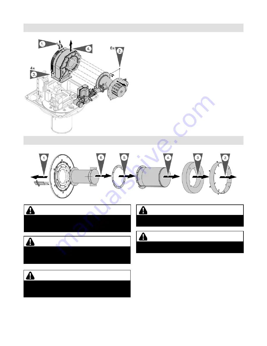
1. Remove the electrodes (if required).
2. Undo 6 screws from the insulation ring.
Torque when installing: 13 lb.in (1.5 Nm.)
3. Remove the insulation ring.
4. Unscrew the burner gauze assembly.
You can now vacuum or replace the burner gauze
assembly. Torque when installing: 7.5 lb.ft (10 Nm.)
5. Replace all gaskets. Reassemble burner tube and burner
in reverse order. Torque: 7.5 lb.ft (10 Nm).
6. Remove the insulation ring.
WARNING
Gas leakage can lead to risk of explosion. Close gas
shut-off valve.
WARNING
Contact with hot surfaces can lead to burn injuries.
Undertake work on the burner only when the system is cold.
CAUTION
Scratches in the combustion chamber can lead to
corrosion. Do not allow any tools or other objects to
fall into the combustion chamber.
CAUTION
Contamination of the burner tube can lead to malfunctions.
When exchanging the burner tube, ensure that no fibres
from the heat insulation block stick to the burner tube.
CAUTION
Improperly executed exchange of the burner tube can lead
to contamination of the combustion chamber. Ensure that the
combustion chamber is maintained free of insulation
fi
bres.
Fan
1. Disconnect both connectors from the fan.
2. Remove 6 nuts on the Venturi pipe. Remove the
Venturi pipe with the fitted gas valve.
Torque when installing: 4.5 lb.ft (6 Nm).
3. Undo the hexagon nuts from the 4 studs.
4. Remove the fan, noting how the gasket is positioned.
5. Installation in reverse order.
Note:
Fit gasket in the correct position.
6. For further steps, see chapter “Further assembly”
on page 117.


