Chapter 1
Xgig1000 System Overview
Xgig1000 8 Port 25G/32G Chassis
Page 68
Xgig1000 Hardware Guide
March 2017
If you use the web initiated chassis upgrade, the user is directed to the Upgrade Status tab
once the upgrade has started. The log displayed in this tab will also indicate the application
install has completed, even though there may be a subsequent blade firmware upgrade
that could last for 15 more minutes. If this process fails, the Status LED is a steady red.
In order to make sure the blade upgrade process is complete, check the Status LED on the
blade, or open the Xgig1000 URL, and select the
Status
tab.
Blade LEDs
There are two LEDs for each port on the blade. The two LEDs are under the control of Xgig
application software.
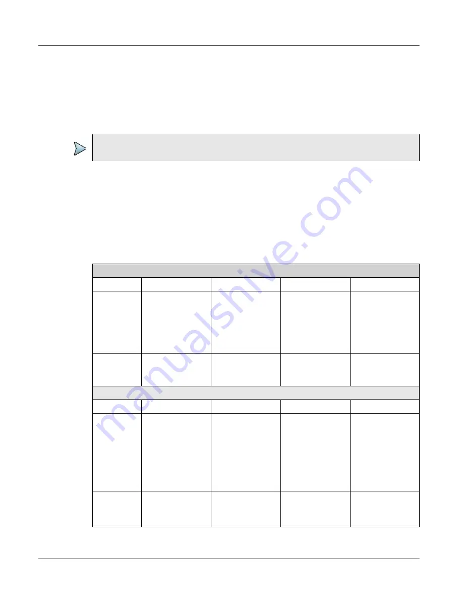
provides a description of the LEDs for the ports of the 8 Port 25G/32G system.
There is one LED of each type for each port on the blade.
NOTE
In the case of a blade upgrade failure, contact the
Table 39
8 Port 25G/32G Blade LEDs
8 Port 25G/32G Blade LEDs for Analyzer Ports
LED
Color Blue
Color Green
Color Orange
OFF
Left LED
Locked
Indicates that
the Analyzer
port is locked for
use by Trace-
Control.
N/A
N/A
Not Locked.
The Analyzer
port is available.
Right LED
N/A
Data present
when blinking
Data present
with Physical
Errors if blinking
Loss of Signal
(No cable or
transceiver)
8 Port 25G/32G Blade LEDs for Jammer Ports
LED
Color Blue
Color Green
Color Orange
OFF
Left LED
Locked
Indicates that
the
Jammer port is
locked for use
by
Xgig Maestro.
N/A
N/A
Not Locked.
The Jammer
port
is available.
Right LED
N/A
Data present
Data present
with
Physical Errors
Loss of Signal
(No cable or
transceiver)


