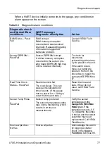
Diagnostics and repair
86
LFXG-H Installation and Operation Guide
LED indicators
CPU board LED indicators
Use the LED indicators on the CPU board to check the basic functioning of
the gauge. They are visible when you remove the explosion-proof housing
pipe cap.
Table 5.7
Power supply LED indicators
LED
Description
Normal
Condition
Error condition
Recommendation
+6 V
+6 V DC
voltage
level to
electronics
ON
OFF – electronics are
not rec6 V DC
voltage required for
functioning.
6 V on test
points. Check fuse
on power supply
board. Check power
input terminals 1, 2.
+24
V
Analog
output loop
voltage
ON
OFF – 24 V not
present on 4 ... 20 mA
output.
4 ... 20 mA output and
HART
communications are
bad.
Check loop wiring
and jumpers JP1,
JP2 on power
supply board.
Replace power
supply board.
Rela
y
Relay
condition
indicator
ON = relay is
energized.
OFF = relay is
de-energized.
None
Check against relay
output terminals 3,
4, and 5. If no relay
output, replace
power supply
board.
CPU LED memory corrupt pattern
FI
EL
D
ME
M
HAR
T
CP
U
AU
X
HV
HV
AU
X
CP
U
HAR
T
ME
M
On
Blinking
Off
Normal LED pattern
Memory corrupt pattern
Note:
If the LED band displays the Memory Corrupt pattern, call /
VEGA Field Service to report this condition. The gauge does
not operate if the FLASH chip is corrupt.
Summary of Contents for FiberFlex LFXG-H
Page 2: ......
Page 4: ...ii LFXG H Installation and Operation Guide NOTES...
Page 6: ...iv LFXG H Installation and Operation Guide...
Page 14: ...Preface xii LFXG H Installation and Operation Guide...
Page 34: ...Installation 32 LFXG H Installation and Operation Guide FiberFlex mounting...
Page 91: ...Diagnostics and repair LFXG H Installation and Operation Guide 89 Source Functions...
Page 100: ...98 LSGH Installation and Operation Guide NOTES...
Page 101: ......


