background image

Installation

LFXG-H Installation and Operation Guide

29

Location considerations

When you ordered the gauge, VEGA sized the source for optimal 
performance. Notify VEGA before installing the gauge if its location differs. 
Satisfactory operation depends on proper location.

Stable temperature

Mount the gauge on a portion of the line where the temperature of the 
process material is relatively stable. Process temperature can affect the 
gauge indication. The amount of the effect depends on:

• Sensitivity of the gauge

• Temperature coefficient of the process material

Protect insulation

Protect from liquid any insulation between the measuring assembly and the 
process. The absorption of a liquid, such as water, can affect the gauge 
indication because it blocks some radiation.

Avoid internal obstructions

The best possible installation of a nuclear level gauge is on a vessel that 
has no internal obstructions (example: agitator, baffle, man ways) directly in 
the path of the radiation beam. If one of these obstructions is present, it can 
shield the radiation from the detector, causing an erroneous reading. 

Note:

Locate the source holder where process material cannot coat it. 
This ensures the continuing proper operation of the source ON/
OFF mechanism (if applicable). Many regulatory bodies 
(example: the U.S. NRC) require periodic testing of the ON/
OFF mechanism.

See the Radiation Safety for U.S. General and Specific 
Licensees, Canadian and International Users Manual and the 
Radiation Safety Manual Addendum of Reference Information 
that came with the source holder and the appropriate current 
regulations for details.

Summary of Contents for FiberFlex LFXG-H

Page 1: ...Operating Instructions LFXG H FiberFlex Detector with GEN2000 Electronics for Level Measurement Document ID 31386 Nuclear...

Page 2: ......

Page 3: ...Register Quality Assurance Limited to the following Quality Management System Standards ISO 9001 2008 ANSI ASQC Q9001 2008 Approval Certificate No 107563 VEGA Americas Inc 4170 Rosslyn Drive Cincinna...

Page 4: ...ii LFXG H Installation and Operation Guide NOTES...

Page 5: ...ounts and levels record 51 Process Chain tab display values 60 Process Variables tab display values 62 Gauge Info tab additional display values 63 Min Max History tab display values 64 Alarm types 73...

Page 6: ...iv LFXG H Installation and Operation Guide...

Page 7: ...ystem overview 21 Source holder 21 Detector assembly 22 Communicating with the gauge 23 Using a field communicator 24 Using Ohmview 2000 Software on a PC 24 Customer Service 26 U S and Canada 26 World...

Page 8: ...od 47 Choosing the linearizer type 47 Table Non linear 48 Table Linear 48 Checking the gauge repeatability 49 Calibration procedures 51 1 Setting the low level and collecting Cal Low data 51 2 Setting...

Page 9: ...ics 73 Gauge Status tab 74 Diagnostic alarms and HART messages 75 Relay Setup tab 75 Gauge status diagnostics screens 75 Acknowledging diagnostic alarms 76 Diagnostic alarm messages 76 Analog alarm 79...

Page 10: ...viii LFXG H Installation and Operation Guide Replacing the CPU or Power supply board 91 Returning equipment for repair to VEGA 94...

Page 11: ...nt or bodily harm On the instrument AC current or voltage A terminal to which or from which an alternating sine wave current or voltage may be applied or supplied DC current or voltage A terminal to w...

Page 12: ...____________________________________ __________________________________ Did you find this manual understandable usable and well organized Please make suggestions for improvement ______________________...

Page 13: ..._____________________________________________________ ____________________________________________________________ ____________________________________________________________ ________________________...

Page 14: ...Preface xii LFXG H Installation and Operation Guide...

Page 15: ...tory body may perform the following to the source holder Dismantle Install Maintain Relocate Repair Test VEGA Field Service engineers have the specific license to install and commission nuclear gauges...

Page 16: ...in the shipment to ensure that the operating handle is in the OFF position If you find the handle in the ON position place it in the OFF position immediately and secure it Note This applies to only so...

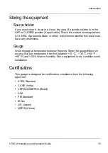
Page 17: ...other to determine whether this area must have any restrictions Gauge Avoid storage at temperatures below freezing Store the gauge indoors in an area that has temperature control between 10 C 35 C 50...

Page 18: ...Introduction 16 LFXG H Installation and Operation Guide Safety Information for EX Areas Please note the EX specific safety information for installation and operation in EX areas IECex Label...

Page 19: ...amma radiation emitter 30 2 year half life Cobalt 60 1 2 and 1 3 MeV gamma radiation emitter 5 3 year half life Power Requirements AC 100 230 10 VAC 90 250 VAC or with internal heater kit 115 230 VAC...

Page 20: ...s A B C and D Div 1 and 2 Class ll Groups E F and G Div 1 and 2 ATEX Certification II 2 G Ex d IIC T6 Gb II 2 G Ex d IIB H2 T6 Gb II 2 D Ex tb IP66 T60 C Db Enclosure rating NEMA 4X IP 66 Ambient temp...

Page 21: ...oop Output Rating 4 20 mA isolated into 250 800 Power Jumper selectable source active or sink passive mode Relay Output Software user settleable Diagnostic alarm or process high low alarm function Rat...

Page 22: ...s Sludge holding tanks Wet wells Principle of operation The gauge receives a shaped or collimated beam of radiation from the source holder through the process material The material in the vessel shiel...

Page 23: ...FiberFlex flexible detector assembly Communication device HART modem with PC and VEGA software or Emerson Field Communicator 375 Source holder A cast or welded steel device that houses a radiation emi...

Page 24: ...flexible detector is a scintillator material which produces light in proportion to the intensity of its exposure to radiation A photomultiplier tube detects the scintillator s light and converts it in...

Page 25: ...T modem and Ohmview 2000 software with a PC to enable Initial setup Calibration Other communication with the gauge You can make a connection anywhere along the 4 20 mA current loop line After setup an...

Page 26: ...he field communicator to use NORM or vapor compensation Using Ohmview 2000 Software on a PC When you use a PC with Windows and a Pentium processor to communicate with the gauge or other VEGA HART tran...

Page 27: ...in Ohmview 2000 software HART Communication Server Launcher program Ohmview 2000 Logger Ohmview 2000 File Configurator Ohmview 2000 Electronic User Manual When you insert the CD the program installs t...

Page 28: ...cies example line shut down because of VEGA equipment you can reach us 24 hours a day Worldwide Contact your local VEGA representative for parts service and repairs Have this information ready VEGA Cu...

Page 29: ...the bench To ensure a quick start up after installation you can test the detector assembly with the HART compatible communication device a field communicator or a PC with a HART modem and VEGA softwa...

Page 30: ...ed to reset the time and date if the gauge has not had power for 28 days The Real Time Clock Fail message may appear You must enter the correct time and date the clock is the basis for source decay ca...

Page 31: ...r can affect the gauge indication because it blocks some radiation Avoid internal obstructions The best possible installation of a nuclear level gauge is on a vessel that has no internal obstructions...

Page 32: ...n the materials change or you introduce new ones the gauge reading can be erroneous Examples Insulation that you add after calibration absorbs the radiation and causes the gauge to erroneously read up...

Page 33: ...itting for applications that must cool the gauge The pole mount requires a nipple and union Note The detector s active area where it is possible to make a level measurement is between 1 25mm from the...

Page 34: ...Installation 32 LFXG H Installation and Operation Guide FiberFlex mounting...

Page 35: ...Housing with Red Threaded Plugs Modified NPT National Standard Pipe Taper openings suitable for A B C and D locations shall be provided The acceptable conduit opening must provide for a 4 full thread...

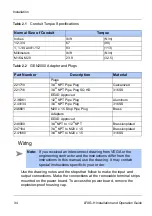
Page 36: ...1 2 83 113 Millimeters lb ft N m M16 M20 23 9 32 5 Part Number Description Material Plugs 221710 3 4 NPT Pipe Plug Galvanized 221716 3 4 NPT Pipe Plug SQ HD 316SS EEXD Approved 2 36361 1 2 NPT Pipe Pl...

Page 37: ...xternal ground screw to connect the power Earth ground wire Remove the top cover the internal ground screw is located at the front of the housing The external ground screw is located next to the condu...

Page 38: ...n For example Terminal 10 6V Auxiliary Input Power may not be used with newer electronics The power input terminals are not polarity sensitive Relay normally open common normally closed L1 AC or DC po...

Page 39: ...or CE compliance install a power line switch 1 m from the operator s control station Output current loop Output signal is 4 20 mA into 250 800 Pin 13 is and Pin 14 is HART communication protocol BEL20...

Page 40: ...mA wires to communicate with the gauge A minimum requirement is a 250 load resistance on the current loop A HART modem may connect across the 4 20 mA wires to enable communication between the gauge an...

Page 41: ...issioning the gauge can include Taking appropriate radiation field tests Checking the pre programmed setup parameters Calibrating on process Verifying the working of the gauge You must remove the sour...

Page 42: ...gic controller PLC chart recorder Ensure that the AC power to the transmitter is a regulated transient free power source UPS type power is the best If using DC power verify that the ripple is 100 mV 1...

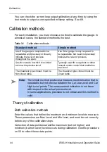
Page 43: ...You must make a calibration on process before the gauge can make accurate measurements Perform the calibration after the installation and commission of the gauge at the field site You do not need to...

Page 44: ...ctions 13 mA and 14 mA Test points H1 and H2 Anywhere along the current loop Make sure there is a 250 800 load on the current loop If no load or an insufficient load exists on the loop it may require...

Page 45: ...lick OK 4 Read the ammeter enter the actual milliamp reading 5 Click OK 6 Click YES if the ammeter reads 4 00 mA or NO for any other reading 7 Repeat until the meter reads 4 00 mA The meter approaches...

Page 46: ...he procedure on 50 to collect these data points Table 3 1 Calibration methods Standard method Simple method Use if the gauge is required to be repeatable and precisely or linearly indicate the level o...

Page 47: ...uces a linear output Standard calibration method This method requires collecting intermediate data points Indicated Level Maximum Level Standard Simple Maximum Level Actual Level Minimum Level Minimum...

Page 48: ...l Low Level and Cal High Level So it is best to take the Cal Low and Cal High samples as close as possible to the Min Level and Max Level to maximize the accuracy within the span Cal Low Counts Cal Hi...

Page 49: ...ernal software calculates a straight line between the Min Level and Max Level based on the Cal Low Level and Cal High Level Choosing the linearizer type The gauge s response curve is non linear due to...

Page 50: ...e calibration process Linearizer data from an earlier model VEGA level gauge Table Linear Use this type for a simple method calibration This type lets you use a linear straight line set of data for a...

Page 51: ...ensor perform a data collection 3 4 times on the same level If the sensor counts vary widely you should increase the Data collection interval parameter Perform a data collection to enable simple measu...

Page 52: ...perform a data collection 1 Select Calibrations Data Collect 2 Click Execute 3 Set the process to a known point 4 Click Start After the data collection the number of counts output by the gauge appears...

Page 53: ...asure the low process level Standard method Simple method Includes these steps see the following pages 1 Setting the low level and collecting Cal Low data 2 Setting the high level and collecting Cal H...

Page 54: ...sel to the low level Have the actual level value ready to enter Procedure 3 4 To set the cal low level Note Perform a data collection for the low and high level within ten days of each other for a goo...

Page 55: ...tual level value ready to enter Procedure 3 5 To set the cal high level 3 Collecting the linearizer table data 4 Enter the actual value in engineering units 5 Click OK Note You must perform a data col...

Page 56: ...so the gauge calculates a response curve based on your data Before collecting the linearizer table data Prepare to set the level and take data for 10 levels including the Cal Low and Cal High levels...

Page 57: ...er curve 2 Collect linearizer data 1 Select Calibration Linearizer Data Pt Create Data Point 2 At the prompt enter the actual known level of process 3 Accept or reject the results when they appear 4 R...

Page 58: ...tering a new measurement span setting into the software Installing a new radiation source holder Moving the gauge to another location Changes to the process vessel example lining insulation or agitato...

Page 59: ...ndardization depends on several factors including the reading s accuracy During the standardization procedure the system displays A default value for the standardization condition A prompt to enter th...

Page 60: ...tallation and Operation Guide Procedure 3 9 To standardize the gauge 1 Select Calibration Standardize 2 Click Execute 3 Click OK 4 Enter the reading 5 Click Start 6 Click Accept 7 Enter the process va...

Page 61: ...se functions are primarily for use by VEGA personnel for advanced troubleshooting and repair Process chain The process chain is a description of the gauge software s calculation of a level measurement...

Page 62: ...Temp Comp Counts The temperature compensated counts that are sensor counts with application of temperature compensation Raw Counts Temperature compensated counts with application of uniformity gain Ad...

Page 63: ...Setup tab A graph of percent count range vs percent process span indicates the non linearity of the radiation transmission s measurement If using a table linearizer the values in the table are percent...

Page 64: ...ermining the Cal low level occurs during the calibration Counts High The temperature and sensor uniformity gain compensated counts from the sensor at the Cal high level Determining the Cal high level...

Page 65: ...ze procedure HV Setting The set point for the sensor high voltage Table 4 2 Process Variables tab display values Value Description Scintillator sensor voltage Firmware version on the FLASH Hardware s...

Page 66: ...ast min max reset Table 4 4 Min Max History tab display values You can reset these values so they record from the time of the reset 1 Select Gauge Info Gauge Info 2 The Gauge Info tab appears Value De...

Page 67: ...nitors both EEPROMs at power up to ensure accurate backups If you install a new CPU board the EEPROM performs a backup of information on the CPU and the sensor boards do not match The software signals...

Page 68: ...you must verify installation in Ohmview 2000 to enable new backups of the EEPROMs Procedure 4 3 To verify the New Hardware Found message When new hardware is not installed If the error message New ha...

Page 69: ...use them in combination to test multiple variable effects All test modes time out after one hour if you do not exit Caution If you suspect an EEPROM is corrupt please call VEGA Field Service for advic...

Page 70: ...l for verifying the current loop calibration To calibrate the current loop see Chapter 3 Calibration Procedure 4 5 To perform a current loop test ailable 1 Select Diagnostics Test Current Loop Test 2...

Page 71: ...ld the source Vary the radiation field While in this mode after entering a number of counts it may be useful to look at the Process Chain tab to view the variables affected by the raw counts value Pro...

Page 72: ...r alarm annunciators are functioning Procedure 4 8 To perform a relay test Temperature Test This mode manually forces the sensor s temperature probe output to a specified value This is useful for veri...

Page 73: ...t Selecting the transmitter s type and location Gauge Setup tab 1 Select Diagnostics Test Temperature Test 2 Click Enter 3 Remove the gauge from control Enter the value of the new temperature to force...

Page 74: ...e local transmitter refers to a gauge that has its sensor electronics and processing electronics all contained in the same housing Set a gauge to Remote if the sensor electronics and processing electr...

Page 75: ...e 5 1 Alarm types Name Description Diagnostic alarm Provides information about the level gauge system and alerts users when periodic procedures are due Analog alarm Sets the current loop mA output to...

Page 76: ...stallation and Operation Guide Gauge Status tab Table 5 2 Alarm type outputs Diagnostic Analog Process X ray Option to trigger relay X X X Display HART message Optional Current loop output affected X...

Page 77: ...2000 screen HART messages that appear when a HART device connects if the diagnostic condition is selected in Alarms Diagnostic Alarm Relay output if it is set as a diagnostic alarm relay in Alarms Re...

Page 78: ...urn off when the problem is solved except these alarms Source wipe due Shutter check due Standardize due Perform the procedure to acknowledge them Diagnostic alarm messages Active alarm messages may a...

Page 79: ...e the alarm Cycle power to the unit If the alarm recurs there is a hardware problem Perform the procedure to repair the corrupted EEPROM on 67 Real Time Clock Status Pass Fail Real time clock fail The...

Page 80: ...cial software Sensor Status Pass Fail Sensor fail 1 count seen in the last 10 seconds Configurable by Field Service Indicates the sensor is malfunctioning Call VEGA Field Service Sensor Voltage Status...

Page 81: ...r disconnection of electrical connections from the sensor assembly to the CPU board New hardware found No Yes New hardware found The CPU board detects a configuration mismatch The CPU board or sensor...

Page 82: ...ple vessel weld inspections often use portable radiographic x ray sources X rays that the gauge detects can cause a false low reading and adversely affect any control based on the gauge output This al...

Page 83: ...or The second detector only monitors x ray interference and has a frequency output that wires to the auxiliary input of the primary detector The primary detector s programming triggers the x ray alarm...

Page 84: ...ormation to determine whether a problem recently occurred and was internally repaired example EEPROM corruption Troubleshooting Two circuit boards in the level gauge are field replaceable he newest er...

Page 85: ...G H Installation and Operation Guide 83 Circuit board identifications Power supply board RS 485 ground if applicable Mounting bracket GEN2000 circuit board identification Internal housing ground screw...

Page 86: ...s Located on the power supply and CPU board Power Supply and CPU Boards Table 5 4 Power supply board test point labels Label Description H1 HART connection H2 HART connection TP1 Isolated ground TP2 L...

Page 87: ...Table 5 5 CPU test point labels Label Description Count Raw input signal coming from the preamplifier GND Logic ground U5 pin 8 5 V power supply test points Referenced to logic ground Note Do not cha...

Page 88: ...board Check power input terminals 1 2 24 V Analog output loop voltage ON OFF 24 V not present on 4 20 mA output 4 20 mA output and HART communications are bad Check loop wiring and jumpers JP1 JP2 on...

Page 89: ...cessing unit on CPU board Blinks at rate of 1 time per second LED does not blink CPU not functioning Check power input Replace CPU board Aux Auxiliary input frequency signal indicator Blinks if auxili...

Page 90: ...ule Description Frequency Procedure Standardize As required by process conditions usually at least once a month Calibration chapter Source holder shutter check Every 6 months unless otherwise required...

Page 91: ...Diagnostics and repair LFXG H Installation and Operation Guide 89 Source Functions...

Page 92: ...change the due date of source wipe or shutter check Field repair procedures Very few parts are field repairable but you can replace entire assemblies or boards These parts are replaceable CPU circuit...

Page 93: ...a replacement is necessary The sensor EEPROM contains a backup of the CPU board EEPROM After replacing the CPU board you must perform a memory backup to update the CPU board s EEPROM with the informat...

Page 94: ...12 Install the plastic electronics cover 13 Install the housing cover 14 Turn on the power to the unit 15 Connect a HART communicator to the unit and verify that the unit is operational Note If you ch...

Page 95: ...Diagnostics and repair LFXG H Installation and Operation Guide 93 Replace Power Supply or CPU Board Mounting Nuts...

Page 96: ...VEGA representative using the information on 26 and ask for repair service 2 VEGA assigns the job a material return authorization MRA number 3 Indicate the MRA on the repair service purchase order 4...

Page 97: ...indicators 86 CPU EEPROM corrupt 67 alarm acknowledge 76 78 in diagnostic history 82 CPU EEPROM status diagnostics check 78 CPU serial number 63 cross talk 30 current loop calibrating on the bench 27...

Page 98: ...s to 66 New Hardware tab 66 new measurement span 56 new process application 56 new radiation source holder 56 non linear table 48 O Obstructions 29 Ohmart Customer Service 26 Field Service 26 Ohmart V...

Page 99: ...mode 69 Sensor voltage 63 Sensor voltage status diagnostics check 78 shutter check frequency 88 recording when complete 90 Shutter check due alarm acknowledge 78 diagnostics check 78 source cross talk...

Page 100: ...98 LSGH Installation and Operation Guide NOTES...

Page 101: ......

Page 102: ...a com www vega americas com 31386 US 150917 Subject to change without prior notice 2015 VEGA Americas Inc Cincinnati Ohio USA All statements concerning scope of delivery application practical use and...

Reviews: