84
DSGH Installation and Operation Guide
Diagnostics and repair
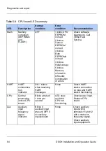
Table 5.8
CPU board LED summary
LED
Description
Normal
condition
Error
condition
Recommendation
Mem
Memory
corruption
(EEPROMs
and
FLASH)
OFF
1 blink: CPU
EEPROM
corrupt
2 blinks:
Sensor
EEPROM
corrupt
3 blinks:
Both
EEPROMs
corrupt
4 blinks:
RAM corrupt
5 blinks:
Memory
mismatch
ON solid:
combination
of errors
Check software
diagnostics. Call
VEGA Field
Service.
HART
HART
communica
tion
indicator
ON
–
blinks
when receiving
HART
messages
None
Check HART
device connection
on loop and HART
device functioning.
CPU
Central
processing
unit on CPU
board
Blinks at rate of
1 time per
second
LED does
not blink.
CPU not
functioning.
Check power input.
Replace CPU
board.
Aux
Auxiliary
input
frequency
signal
indicator
Blinks if
auxiliary input
present. OFF if
no auxiliary
input present
None
Check auxiliary
input wiring
terminals 11 and 12
with a meter for
frequency signal.
Check auxiliary
input equipment.
Summary of Contents for DSGH
Page 2: ......
Page 4: ...2 DSGH Installation and Operation Guide NOTES ...
Page 8: ...6 DSGH Installation and Operation Guide NOTES ...
Page 12: ...10 DSGH Installation and Operation Guide Preface NOTES ...
Page 32: ...30 DSGH Installation and Operation Guide Installation Mounting the DSGH gauge ...
Page 56: ...54 DSGH Installation and Operation Guide Calibration NOTES ...
Page 94: ...92 DSGH Installation and Operation Guide Diagnostics and repair NOTES ...
Page 98: ...96 DSGH Installation and Operation Guide NOTES ...
Page 99: ......

