82
DSGH Installation and Operation Guide
Diagnostics and repair
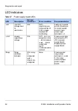
LED indicators
Table 5.7
Power supply board LEDs
LED
Description
Normal
Condition
Error condition
Recommendation
+6 V
+6 V DC
voltage level
to
electronics
ON
OFF –
electronics are
not rec6
V DC voltage
required for
functioning.
6 V on test
points. Check fuse
on power supply
board. Check
power input
terminals 1, 2.
+24 V
Analog
output loop
voltage
ON
OFF – 24 V not
present on 4 mA
... 20 mA output.
4 mA ... 20 mA
output and
HART
communications
are bad.
Check loop wiring
and jumpers JP1,
JP2 on power
supply board.
Replace power
supply board.
Relay
Relay
condition
indicator
ON = relay
is
energized.
OFF =
relay is de-
energized.
None
Check against
relay output
terminals 3, 4, and
5. If no relay
output, replace
power supply
board.
Summary of Contents for DSGH
Page 2: ......
Page 4: ...2 DSGH Installation and Operation Guide NOTES ...
Page 8: ...6 DSGH Installation and Operation Guide NOTES ...
Page 12: ...10 DSGH Installation and Operation Guide Preface NOTES ...
Page 32: ...30 DSGH Installation and Operation Guide Installation Mounting the DSGH gauge ...
Page 56: ...54 DSGH Installation and Operation Guide Calibration NOTES ...
Page 94: ...92 DSGH Installation and Operation Guide Diagnostics and repair NOTES ...
Page 98: ...96 DSGH Installation and Operation Guide NOTES ...
Page 99: ......


