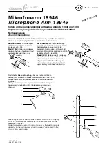


Verbindungsrohr 5 des Mikrofonarms in gewünschter Höhe und Neigung
mittels Klemmschraube 6, Rastscheibe 7 und Feder 8 an Rastschelle
befestigen- siehe Abb.
Fasten connecting tube 5 of the microphone arm at the height and angle
desired using the locking screw 6, locking washer 7 and spring 8 to the
slip-on clamp- see drawing.
-18946.300.55-
-03.80.276.00- 12/00
5
6
7
8
Mikrofonarm 18946
Microphone Arm 18946
höhen- und neigungsverstellbar für Keyboardständer 18940 und 18990
height and angle adjustable for keyboard stands 18940 and 18990
Montageanleitung
Assembly Instructions
Hintere Abschlußstopfen an den Auflagerohren des Keyboardständers entfernen:
Remove upper plastic plugs from the backside of the keyboard stand:
bei Modell 18940:
Gummiauflagen
(2 Stück) mind. 40 mm nach vorne
schieben- siehe Abb.
Model 18940:
Slide the two sleeves
down on the tube of keyboard stand
approximately two inches- see
drawing.
bei Modell 18990:
Eine Gummiauflage
mind. 40 mm nach vorne schieben, andere
Gummiauflage entfernen und durch
beigefügte Gummiauflage mit Ausschnitt
ersetzen (40 mm Mindestabstand zum Roh-
rende beachten!)- siehe Abb.
Model 18990:
Replace one of the sleeves
with extra provided sleeve. Place cut out
sleeve onto open ended tube closest to
diagonal brace. Slide the other regular
sleeve down on tube of keyboard stand
approximately two inches- see drawing.
mind.
40 mm
two
inches
two
inches
mind.
40 mm
Made in Germany
Rastschelle 1
bis zum Anschlag
über das Keyboardständer-
Auflagerohr schieben und mittels Innensechskantschraube 3 und
Sicherungsmutter 2 mit Innensechskantschlüssel 4
fest
fixieren-
siehe Abb.
Place geared clamp 1 onto keyboard stand end tube. Using allen
head screw 3 and locking nut 2, tighten clamp securely- see
drawing.
1
2
3
4