background image

PaX-i (PCH-2500) User Manual

24

3. PaX-i Imaging System Overview

The CE symbol grants this equipment compliance with the European 
Directive for Medical Devices 93/42/EEC as amended by 2007/47/EC as a 
class IIb device.

This equipment received the CSA certification mark in accordance with 
CAN/CSA C22.2 No.601.1 regulations.

Classifications (IEC60601-1 6.1):

Protection against the ingress of water: Ordinary Equipment: IPX0

Protection against electric shock: Class 1 equipment, Type B Applied Parts


3.2 

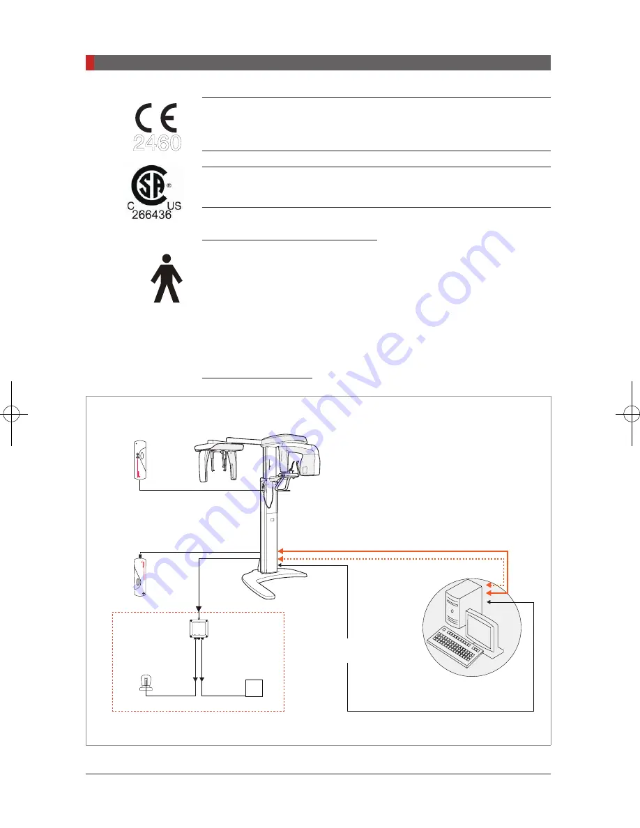
Imaging System Structure

Case A: LVDS Cable

PC w/ imaging and

image viewer programs

Exposure switch

UP/DOWN switch

(Optional)

Frame grabber cable(L

LAN cable(OS:optional)

VDS): 7 m(23’)

RS232 serial

cable 10 m(32.8’)

Warning system panel

Warning lamp

Door interlock

LAMP INPUT

LAMP OUTPUT

SIGNAL INPUT

WARNING SYSTEM BOX

(Optional)

PaX-i

2460

Pi_u272_en_20180514.indd   24

2018-05-14   오전 11:03:10

Summary of Contents for PAX-I

Page 1: ...User Manual Full version Model PCH 2500 Version 2 72 English...

Page 2: ......

Page 3: ...i stands for innovation one of the core values of VATECH which aims to expand accessibility of medical solutions to more people...

Page 4: ...7 2 4 Warnings 18 3 PaX i Imaging System Overview 22 3 1 Introduction 22 3 1 1 System Components 22 3 1 2 Features 22 3 1 3 The PaX i Options 23 3 1 4 Standards and Regulations 23 3 2 Imaging System S...

Page 5: ...atient Records 56 5 3 Initiating the Imaging Program 57 6 Acquiring PANO Images 60 6 1 PANO Imaging Program 60 6 2 Setting Exposure Parameters 65 6 3 Positioning the Patient 68 6 3 1 Pano Standard Mod...

Page 6: ...ental Specifications 120 1 Recommended X Ray Exposure Table 120 2 X Ray Dose Data 122 2 1 DAP Table 122 2 2 X ray Leakage Dose 123 2 3 X Ray Scatter Dose 125 3 Electromagnetic Compatibility EMC Inform...

Page 7: ...General Information 1 1 1 Notice 08 1 2 Manufacturer s Liability 09 1 3 Owner and Operator s Obligations 09 1 4 Conventions in this Manual 10...

Page 8: ...d warnings which appear in this manual The QR code linked to video file about image capture for the PANO Standard and CEPH Lateral is provided in the manual The smartphone and pad which have the QR co...

Page 9: ...used normally in accordance with the user s manual The equipment damage or malfunction is not the result of an error on the part of the owner or operator 1 3 Owner and Operator s Obligations The owner...

Page 10: ...ollowed with the utmost care Failure to comply with a warning may result in severe damage to the equipment or physical injury to the operator and or patient CAUTION CAUTION Indicates a situation that...

Page 11: ...Warnings and Precautions 2 2 1 General Safety Precautions 12 2 2 Electricity related Safety Precautions 16 2 3 Radiation Safety 17 2 4 Warnings 18...

Page 12: ...emedy such irregularities General safety precautions Follow the instructions specified in this manual to ensure the safety of both the patient and the operator The operator must maintain visual contac...

Page 13: ...not obstruct the equipment s ventilation for air opening Improper ventilation could result in the equipment overheating due to a lack of air circulation Do not spray any type of liquid or aerosol on t...

Page 14: ...elapse between each image acquisition Mode of operation Continuous operation with intermittent loading Exposure time Max 20 2 s Resting time 5 min Column operation time 1 min Resting time 9 min If the...

Page 15: ...erform X rays of patients if the system is in full working order Always ensure that equipment movement is not obstructed by the patient s clothing a medical device such as a wheelchair or the patient...

Page 16: ...ircuit for the PC and the equipment Combining this equipment with other devices Do not connect this equipment to devices which are not part of the system Do not connect this equipment to a Multiple Po...

Page 17: ...ain outside a shielded room during X Ray exposure in order to protect himself herself from radiation The patient must wear a lead apron with neck and thyroid protection during X Ray exposure Children...

Page 18: ...ators ICDs If the patient has such an implantable device you should be aware of any interference in its operation and immediately power off the Dental X ray system PaX i system is designed to withstan...

Page 19: ...near this equipment Do not operate the PC or Touchscreen while the equipment is performing an operation Failure to comply with this instruction may result in system malfunction Immediately stop imagin...

Page 20: ...e device on a flat surface to maintain stability If the equipment is not stable property damage and or personal injury may occur Do not push or pull the equipment Equipment should only be installed by...

Page 21: ...tandards and Regulations 23 3 2 Imaging System Structure 24 3 3 General View of the PaX i 27 3 3 1 Laser Beams 29 3 3 2 The Exposure Switch 29 3 3 3 Emergency Stop Button 30 3 3 4 Components and Posit...

Page 22: ...y of the image in 2D of the head region including the dental maxillofacial regions for planning and diagnostics The system includes the following software packages EasyDent for 2D viewing and patient...

Page 23: ...acts are minimized to improve image quality CAN Controlled Area Network is employed to provide reliability and dependability 3 1 3 The PaX i Options The following options are all based on the PaX i It...

Page 24: ...ulations Classifications IEC60601 1 6 1 Protection against the ingress of water Ordinary Equipment IPX0 Protection against electric shock Class 1 equipment Type B Applied Parts 3 2 Imaging System Stru...

Page 25: ...ort D Video out E Frame grabber cable LVDS Case B LAN Cable PC w imaging and image viewer programs PaX i Warning system panel Warning lamp Door interlock LAMP INPUT LAMP OUTPUT SIGNAL INPUT WARNING SY...

Page 26: ...optional NOTE Equipment connected to the signal input signal output or other connectors must comply with the relevant IEC standards e g IEC60950 for IT equipment and IEC60601 1 series for medical ele...

Page 27: ...OR TELESCOPIC COLUMN COLUMN UP DOWN SWITCH OPTIONAL COLUMN UP DOWN BUTTON LASER BEAM ON OFF BUTTON ON OFF SWITCH BASE X RAY TUBE CHIN SUPPORT HANDLE FRAME STATIONARY COLUMN TEMPLE SUPPORT EMERGENCY SW...

Page 28: ...ging X RAY TUBE The source of X Ray emission TEMPLE SUPPORT Supports the patient s temples during PANO scan CHIN SUPPORT Supports the patient s chin during imaging COLUMN Up down BUTTON Moves the Colu...

Page 29: ...r beam 3 Canine laser beam 3 3 2 The Exposure Switch The exposure switch allows the operator to control image acquisition from outside of the X Ray room Press and hold the exposure switch down until a...

Page 30: ...exposure switch has been released Injury to the patient or damage to the equipment Other emergency situations If a problem occurs during image acquisition press the red emergency stop button to immedi...

Page 31: ...which come into direct contact with the patient such as the bite block chin support or temple supports using an alcohol based solution and allow them to dry before use Accessories Order No Chin suppor...

Page 32: ...ending on the purchase option chosen Version Mode Option Basic PANO examination Special examination Intelligent PANO examination Special examination AF Auto focus optional UHD PANO examination Special...

Page 33: ...1 Right 10 1 6 7 5 1 Front 16 7 11 1 8 4 Left 10 1 6 7 5 1 Wide Standard 20 2 13 5 10 1 Right 10 1 6 7 5 1 Front 16 7 11 1 8 4 Left 10 1 6 7 5 1 Child Standard 17 2 11 5 8 6 Right 8 6 5 7 4 3 Front 13...

Page 34: ...pe Sensor optional Examination Modes Scan Time s Lateral PA SMV Waters View Carpus 12 94 Full Lateral optional 16 9 One shot Type Sensor optional Examination Modes Scan Time s Lateral 0 9 PA SMV Water...

Page 35: ...ct complies with the European Directive for Medical Devices 93 42 EEC as amended by 2007 47 EC as a class IIb device Label CSA mark No 266436 Label Address where the equipment was manufactured Label T...

Page 36: ...view Symbols Description Location Caution Federal law restricts this device to sale by or on the order of a licensed healthcare practitioner Label Indicates that the user needs to refer to the Instruc...

Page 37: ...bel is attached to the right side of the equipment and it consists of 5 parts as below No Item 1 Main Label 2 CAUTION Label X ray Attention X ray on when equipment in operation 3 X RAY GENERATOR Label...

Page 38: ...This page is left intentionally blank...

Page 39: ...Software Overview 4 4 1 PC System Requirements Recommended 40 4 2 EasyDent 41 4 3 Imaging Software Overview 42 4 3 1 PANO Mode 47 4 3 2 CEPH Mode 51...

Page 40: ...following table If necessary upgrade your PC s system configuration to meet the following specifications DO NOT place the PC or peripheral equipment connected to the PC in the immediate vicinity of t...

Page 41: ...yDent As the basic imaging platform for all VATECH dental X Ray equipment EasyDent is designed to be easy to use The Imaging Program is interfaced with EasyDent Images acquired by the Imaging Program...

Page 42: ...enshot shows the main interface in PANO mode For details concerning PANO and CEPH imaging refer to sections 4 3 1 4 3 2 A Imaging Mode Display This displays the current imaging mode NOTE Indicates tha...

Page 43: ...Imaging Guide Window This displays various text instructions for the operator to follow E Scan Time and DAP Display Window Upon clicking Confirm the scan time and estimated DAP value are displayed in...

Page 44: ...Woman H X ray intensity This tool selects X ray intensity NOTE Depending on the circumference of the patient s head X ray intensity may be classified as Hard Normal or soft Soft Normal Hard Age Group...

Page 45: ...on 4 Align the Phantom Jig and click the Ready button 5 Press and hold down the exposure switch J Laser Beam On Off Button Use this icon to turn the laser beam on or off for patient positioning This b...

Page 46: ...CEPH imaging modes N Confirm After confirming all settings required for scanning press Confirm to apply the settings NOTE When you click Confirm the scan time and estimated DAP Dose Area Product value...

Page 47: ...e AF B Image Quality One of three modes UHD HD or Normal can be selected for PANO imaging UHD Image with an Ultra high resolution HD Image with higher resolution than Normal Mode Normal Normal image N...

Page 48: ...inimized D PANO Examination Acquire the image for a specific ROI in panoramic mode Mode Region of Interest PANO Image Remark Standard Imaging standard images Supported by any arch type selection Right...

Page 49: ...k Standard Imaging PANO Standard image Supported by any arch type selection Right Imaging PANO lateral right Front Imaging PANO frontal area Left Imaging PANO lateral left Bitewing Bitewing imaging Le...

Page 50: ...mouth open TMJ LAT Close Takes a side view image of the TMJ with the mouth closed TMJ PA Open Takes a posterior anterior image of the TMJ with the mouth open TMJ PA Close Takes a posterior anterior i...

Page 51: ...ng S W comes with the equipment for the CEPH mode examination One shot Type Scan Type 1 CEPH Examination Select the imaging mode Lateral PA SMV Waters View or Carpus Mode Details Lateral Full Lateral...

Page 52: ...ne shot Type Sensor optional Examination Modes Scan Time s Default Lateral 0 9 PA SMV Waters View Carpus 1 2 NOTE Exposure time can be adjusted by resolution of 0 1 s in the range of 0 7 s to 1 2 s On...

Page 53: ...Getting Started 5 5 1 Turning on the PaX i 54 5 2 Running the Image Viewer EasyDent 55 5 2 1 Creating a New Patient Record 55 5 2 2 Retrieving Patient Records 56 5 3 Initiating the Imaging Program 57...

Page 54: ...PORTANT If it has not been used for a long time allow at least an hour before the first exposure since turning on the equipment CAUTION Condensation could form inside the equipment if it is a differen...

Page 55: ...yDent icon or click Start All Programs EasyDent The EasyDent main window will be displayed Go to the section 5 2 1 5 2 2 to create or open an existing patient record NOTE For a detailed guide to using...

Page 56: ...umber First Name and Last Name are required fields which must be filled in All other fields are optional but it is recommended that they are filled in D Click Add to save the patient record 5 2 2 Retr...

Page 57: ...e patient by clicking the mouse on the virtual keyboard and click the Enter The physical keyboard can be used to do the same job C Patient information can be displayed on the Patient information pane...

Page 58: ...tarted B The following imaging program window opens The sole purpose of this window is to control equipment settings and acquire images Please proceed to the next chapter NOTE Refer to chapters 6 7 fo...

Page 59: ...PANO Imaging Program 60 6 2 Setting Exposure Parameters 65 6 3 Positioning the Patient 68 6 3 1 Pano Standard Mode QR Code 69 6 3 2 TMJ Open Mode 73 6 3 3 TMJ Close Mode 76 6 3 4 Sinus Mode 77 6 4 In...

Page 60: ...s outlined there before proceeding with this chapter 6 1 PANO Imaging Program EXAMINATION ARCH SELECTION EXAMINATION PROGRAM PANO EXAMINATION Narrow Standard Right Front Left Normal Standard Right Fro...

Page 61: ...for the patients with the V shaped arch trajectory typically for some females Normal_Standard A panoramic imaging mode for the adult patients with the normal arch trajectories Wide_Standard A panorami...

Page 62: ...mic imaging mode for the child arch trajectory in which case the X Ray exposure is 40 less than that in Normal mode Orthogonal_Standard A panoramic imaging mode to minimize the overlapped region of th...

Page 63: ...de Cons TMJ and parts of an image of the maxillary sinus are not acquired TMJ LAT Open Close An imaging mode to acquire a lateral image of the TMJ in which the X Ray beam is directed on the lateral TM...

Page 64: ...AT A special imaging mode to acquire a Sinus image in which X Ray beam is directed on the lateral region of the maxillary sinus Sinus PA A special imaging mode to acquire a Sinus image in which X Ray...

Page 65: ...Imaging Software Overview A Choose an imaging mode under Imaging Mode B Select the mode under PANO Type Normal or Magic PAN Mode Details Normal Normal image Magic PAN Image with ultra high resolution...

Page 66: ...mages in the ROI If the orthogonal arch is selected its sub modes are activated E Select the ROI for panoramic image acquisition under PANO Examination F Th e pa tient s gender w ill be automatically...

Page 67: ...in blinking to show that it has been activated This means that the equipment is ready for X Ray exposure The rotating unit will move to its initial scanning position Three laser beams Mid sagittal pla...

Page 68: ...dle frame Column up down switch optional NOTE In general imaging is performed with the patient in an upright position However a stool may be used for imaging patients with special circumstances If a s...

Page 69: ...or the bite block is intended for single use only Always replace the hygiene cover for each new patient C Loosen the temple supports by turning the temple support wheel D Guide the patient facing the...

Page 70: ...should be straight and upright H Have the patient bite the bite block along its grooves using his her upper and lower incisors for edentulous patients use the edentulous chin support I Have the patien...

Page 71: ...as this could severely damage the patient s vision A Mid sagittal plane laser beam Position the Mid sagittal plane laser beam on the center of the patient s face to prevent magnifications of the left...

Page 72: ...atient s head using the temple support wheel The temple support wheel is located underneath the patient support rest B Click the Ready button on the GUI or Touchscreen after the patient has been prope...

Page 73: ...ith a large head circumference Man Woman mode may be selected instead of Child Positioning the patient A Insert the TMJ chin support CAUTION Disinfect the chin support using an alcohol based cleaning...

Page 74: ...at the patient s shoulders remain level and that his her neck is relaxed The cervical spine should be straight and upright Ask the patient to remain still until scanning is complete CAUTION To acquire...

Page 75: ...patient s head so that the Frankfurt plane is aligned with the Frankfurt plane laser beam C Canine laser beam Position the canine laser beam on the left corner of the patient s lips Completing Patient...

Page 76: ...en imaging The positions are the same for both modes except for the position of the lips A Shortly after TMJ Open imaging has been completed you will receive the following message Do you want to take...

Page 77: ...n the temple supports by turning the temple support wheel C Guide the patient facing the chin support to the equipment Have the patient stand upright in the center of the equipment D Adjust the height...

Page 78: ...k the patient to remain still until scanning is completed CAUTION To acquire the best image possible ask the patient not to Breathe or swallow saliva during image acquisition Move during image acquisi...

Page 79: ...djusting the Frankfurt plane laser beam lever C Canine laser beam Have the patient smile to properly position the canine laser beam on the center of the patient s canine tooth Completing Patient Posit...

Page 80: ...ly stop all moving parts and cut off all power to the equipment s electrical components You may then safely release the patient from the equipment To reset this button turn it clockwise until it pops...

Page 81: ...y irradiation ensure that The LED lamp on top of the equipment turns orange to indicate X Ray emission The warning lamp outside the X Ray room turns on The sound beep or music optional goes off The ra...

Page 82: ...f the 2 or 5 images taken can be saved This option can be selected by the user from the settings screen by following the process below Settings PANO CEPH Multi focusing setting Select 2 or 5 images Sa...

Page 83: ...ll be automatically transferred to EasyDent Clicking the patient s name in the patient list after imaging will refresh the image list for that patient The patient s most recent image will appear on th...

Page 84: ...4 6 Acquiring PANO Images After Image Acquisition After acquiring the image complete the following steps Loosen the temple supports to release the patient Remove the hygiene cover from the bite block...

Page 85: ...7 1 Setting the Exposure Parameters 86 7 2 Positioning the Patient 89 7 2 1 Lateral Mode QR Code 90 7 2 2 Frontal Mode PA 92 7 2 3 SMV Mode 94 7 2 4 Waters View Mode 95 7 2 5 CARPUS Mode 96 7 3 Initi...

Page 86: ...EPH imaging refer to section 4 3 2 CEPH Mode Depending on the sensor type employed one of two kinds of imaging S W comes with the equipment for the CEPH mode examination One shot type sensor Scan type...

Page 87: ...s defined as a person who is younger than 12 years old If Child is selected the image size and exposure dose are automatically reduced E Select X ray intensity NOTE X ray intensity Hard Normal Soft is...

Page 88: ...t it is activated This means that the equipment is ready for X Ray exposure The CEPH sensor and the 2nd collimator enter positioning mode The scan time and estimated DAP Dose Area Product value are sh...

Page 89: ...It is strongly recommended that the patient wear a lead apron for protection against any possible scatter radiation Adjust the column height to the patient s height using the up down button or switch...

Page 90: ...operator to easily identify the position of the porion on the image B Guide the patient to the CEPH unit C Ask the patient to stand upright Make sure that the patient s shoulders are level and that th...

Page 91: ...should be parallel to the floor F Position the nasal positioner on the patient s Nasion point The height of nasal positioner can be adjusted G Ask the patient to swallow saliva and remain still with...

Page 92: ...al position B Widen the distance between the two ear rods NOTE Porion position reference indicator enables the operator to easily identify the position of the porion on the image C The nasal positione...

Page 93: ...ient s height fit the ear rods along the patient s ear canals G The ear rods should fit properly along the patient s ear canals The patient s Frankfurt Plane should be parallel to the floor H Ask the...

Page 94: ...cting the image acquisition C Guide the patient to the CEPH unit D Ask the patient to stand upright facing the secondary collimator Make sure that the patient s shoulders are level and that his her ne...

Page 95: ...2 4 Waters View Mode Follow the procedure below to prepare and position the patient for Waters View mode image acquisition A Widen the distance between the two ear rods B The nasal positioner should...

Page 96: ...d until X Ray exposure is complete H Click the Ready button after the patient has been properly positioned No X Ray will be emitted at this point The CEPH sensor and the 2nd collimator will move to ca...

Page 97: ...k the patient to put his her right hand flat on the CARPUS plate It is important to ensure that the patient does not bend his her fingers B Have the patient close their eyes and remain still until sca...

Page 98: ...the power to the equipment s electrical components You may then proceed to release the patient safely from the equipment To reset the emergency button turn it clockwise until it pops up WARNING Do no...

Page 99: ...ional goes off The radiation symbol on the upper left corner of GUI turns yellow to indicate X rays are being emitted The image appears in real time on the imaging GUI C Click the Save button to save...

Page 100: ...on the image to enlarge it for viewing or to check its quality After Image Acquisition After the image has been acquired perform the following tasks Fold away the nasal positioner Loosen the ear rod...

Page 101: ...Troubleshooting 8...

Page 102: ...it is ready for capturing the imaging program If imaging cannot be performed Cause Solution Initialization status Wait until the equipment has initialized and then try again If this problem persists r...

Page 103: ...Cleaning and Maintenance 9 9 1 Cleaning 104 9 2 Maintenance 105...

Page 104: ...e cleaning products which contain silicon as they could potentially damage the equipment s electrical components The following table summarizes the standard cleaning procedures to be performed by the...

Page 105: ...quipment For the technical assistance contact VATECH service center or your local VATECH representative Maintenance Task Checklist Maintenance Tasks Maintenance period Before the operation ensure that...

Page 106: ...Confirm that activating the emergency stop button ceases the unit s operation Pressing the emergency stop button should stop all equipment movements and X Ray emission Weekly Ensure that all visible...

Page 107: ...Disposing of the Unit 10...

Page 108: ...disposal regulations IEC 60601 1 6 8 2 j Part Material Recyclable Waste Disposal Site Hazardous waste Needs Separate Collection Frame and covers Aluminum and plastics Motors Circuit boards Cables and...

Page 109: ...Technical Specifications 11 11 1 Mechanical Specifications 110 11 2 Technical Specifications 113 11 3 Electrical Specifications 117 11 4 Environmental Specifications 118...

Page 110: ...agnification Mode FDD mm FOD mm ODD mm Magnification PANO 490 3 375 5 114 8 1 3 constant CEPH 1 745 1 524 221 1 14 constant FDD Focal Spot to Detector Distance FOD Focal Spot to Object Distance ODD Ob...

Page 111: ...PaX i PCH 2500 User Manual 111 11 Technical Specifications With Cephalometric Unit Non Base type Unit mm Inches Without Cephalometric Unit Base type Unit mm Inches...

Page 112: ...PaX i PCH 2500 User Manual 112 11 Technical Specifications With Cephalometric Unit Base type Unit mm Inches Common Dimension Non Base type Common Dimension Base type Unit mm Inches...

Page 113: ...CEPH unit 990 L x 1125 W x 2320 H 38 98 L x 44 29 W x 91 34 H in With CEPH unit Scan Type 1920 L x 1125 W x 2320 H 75 6 L x 44 29 W x 91 34 H in With CEPH unit One shot Type 1930 L x 1125 W x 2320 H 7...

Page 114: ...IEC60336 Target Angle 5 Inherent Filtration At least 0 8 mm Al eq at 50 kV X ray Coverage 95 x 380 mm at SID 550 mm Anode Heat Content 35 kJ Duty Cycle 1 60 or more Exposure time interval time Maximum...

Page 115: ...0 20 25 15 0 2 9 3 0 3 1 3 2 3 3 3 4 3 5 Constant potential high voltage generator Nominal Focus Spot Value 0 5 TUBE CURRENT mA 100kV Ef 80kV 50kV FILAMENT CURRENT A FILAMENT VOLTAGE V Anode Thermal C...

Page 116: ...PaX i PCH 2500 User Manual 116 11 Technical Specifications Tube Housing Assembly Thermal Characteristics Tude Anode Thermal Characteristics...

Page 117: ...e 300 fps 200 fps 240 fph Sensor size mm 175 4 x 86 x 21 6 251 2 x 69 x 27 1 402 x 364 x 32 A D bits 14 11 3 Electrical Specifications Item Description Power supply voltage AC 100 120 V 200 240 V AC 1...

Page 118: ...11 4 Environmental Specifications Item Description During operating Temperature 10 35 Relative humidity 30 75 Atmospheric pressure 860 1060 hPa Transport and storage Temperature 10 60 Relative humidi...

Page 119: ...Electromagnetic Compatibility EMC Information 126 4 Acquiring image for the pediatric dental patient 130 4 1 Age group classification table 130 4 2 Positioning the pediatric dental patient 130 4 3 Se...

Page 120: ...8 72 8 71 8 Child 68 8 67 8 66 8 B CEPH mode Lateral Hard kVp mA Normal kVp mA Soft kVp mA Sensor Type One shot Scan One shot Scan One shot Scan Man 90 10 86 10 90 10 85 10 89 10 84 10 Woman 90 10 85...

Page 121: ...Vp mA Normal kVp mA Soft kVp mA Man Woman Child 60 6 60 5 60 4 NOTE Maximally allowed tube voltage current kVp 10 mA 20 according to IEC60601 2 7 Due to image optimization performed prior to shipping...

Page 122: ...r or other staff the PaX i is designed to comply with IEC 60601 1 3 Part 1 General Requirements for Safety Test Condition Model Brand Name PCH 2500 PaX i Sensor type PANO Xmaru 1501CF CEPH Xmaru 2301C...

Page 123: ...Test Equipment Information Instrument Manufacturer Model S N Dose Meter Victoreen 660 101114 101377 Test Condition Test mode Detector kVP mA sec PANO HD Adult Xmaru 1501CF 90 10 13 5 PANO HD Child 11...

Page 124: ...6 26 6 140 17 3 16 2 17 6 30 2 150 18 5 17 0 22 1 33 7 160 21 2 17 5 23 5 67 8 170 23 0 16 7 25 5 36 8 180 6 1 4 7 5 2 19 9 190 16 4 10 8 16 9 26 9 200 20 7 18 2 23 7 30 6 210 50 7 13 3 15 6 29 3 220...

Page 125: ...e Tested PANO UHD Distance from focal point m 1 Applied Tube Voltage Peak kVp 90 Applied Tube Current mA 10 Mode Direction PANO UHD 16 6 s mR hr 1 m 3 3 ft 1 5 m 4 9 ft 2 m 6 6 ft 0 15 3 9 76 2 32 45...

Page 126: ...combination with the shielded location The model PaX i PCH 2500 must be used only in a shielded location with a minimum RF shielding effectiveness and for each cable that exits the shielded location...

Page 127: ...w e r q u a l i t y should be that of a typical commercial or hospital environment Surge IEC 61000 4 5 1 kV line s to line s 2 kV line s to earth 1 kV line s to line s 2 kV line s to earth M a i n s...

Page 128: ...electromagnetic environment Immunity test IEC 60601 test level Compliance level Electromagnetic environment guidance Conducted R F I E C 61000 4 6 Radiated RF IEC 61000 4 3 3 V r m s 150 kHz to 80MHz...

Page 129: ...ess telephones and land mobile radios amateur radio AM and FM radio broadcast and TV broadcast cannot be predicted theoretically with accuracy To assess the electromagnetic environment due to fixed RF...

Page 130: ...patient Use a cotton roll to fill in missing primary teeth or partially erupted permanent teeth Adapt adult recommendation for the direction of laser light beam guide for use with primary teeth Observ...

Page 131: ...f radiographs in children P40 48 European Journal of Pediatric Dentistry 1 2003 Guidelines in dental radiology are designed to avoid unnecessary exposure to X radiation and to identify individuals who...

Page 132: ...Ray imaging Several studies have investigated the radiation doses involved in dental CBCT for adults but none has looked into pediatric doses This study estimates the organ and effective doses to two...

Page 133: ...ithin a standard 6 year old anthropomorphic phantom Organ and effective doses of brain CT were evaluated for 19 protocols in nine hospitals on various 2 320 detector rows MDCT scanners Results The max...

Page 134: ...nt Under Test FDD Focal spot to Detector Distance FOD Focal spot to Object distance FOV Field of View FPD Flat Panel Detector IEC International Electro technical Commission ISO International Standards...

Page 135: ...st current information contact your VATECH representative Manufactured by VATECH Co Ltd Tel 82 1588 9510 Email gcs vatech co kr Website www vatech co kr Headquarters 13 Samsung 1 ro 2 gil Hwaseong si...

Page 136: ......

Page 137: ...Postal code 18449 13 Samsung 1 ro 1 gil Hwaseong si Gyeonggi do Korea www vatech co kr...

Reviews: