ProStar325 Service Manual
Publication date 8 May 2003
111
loose at this point to allow for optimization.
•
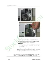
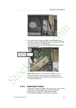
Remove the Power Supply assembly to enable access to the
connector sitting underneath (P16). This is on the Control PWB
and it is where the Vis lamp plugs into.
Connect the Vis lamp and return the Power Supply assembly to
its original position.
Note:
Whenever the Vis lamp option is installed, you are
required to perform a 0%T calibration as described in the
Diagnostics section. Do this after you have optimized the Vis
lamp as described below.
5.4.1
Optimizing Vis lamp
To optimize the light throughput of the Vis lamp, you will need to
connect the ProStar325 detector to a local PC, establish
communication, and open the Diagnostics software.
Then, switch the detector on and allow it to initialize.
Connect Vis
lamp to P16
StockCheck.com
Summary of Contents for ProStar 325 UV-Vis
Page 9: ...ProStar325 Service Manual Publication date 8 May 2003 9 S t o c k C h e c k c o m ...
Page 19: ...ProStar325 Service Manual Publication date 8 May 2003 19 S t o c k C h e c k c o m ...
Page 34: ...ProStar325 Service Manual 34 Publication date 8 May 2003 S t o c k C h e c k c o m ...
Page 71: ...ProStar325 Service Manual Publication date 8 May 2003 71 S t o c k C h e c k c o m ...
Page 72: ...ProStar325 Service Manual 72 Publication date 8 May 2003 S t o c k C h e c k c o m ...
Page 118: ...ProStar325 Service Manual 118 Publication date 8 May 2003 S t o c k C h e c k c o m ...
Page 149: ...ProStar325 Service Manual Publication date 8 May 2003 149 S t o c k C h e c k c o m ...


