ProStar325 Service Manual
90
Publication date 8 May 2003
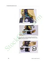
mains supply input cables are still connected. Place the
power supply module in the service position as shown below,
and fasten in this position using the screw which originally
held it in place.
The Processor PWB will now be exposed.
•
Disconnect all cables from the Processor PWB.
•
The PWB can now be removed along with its mounting
bracket.
Replacement
When a new replacement Processor PWB is received, it will be
accompanied by two labels;
•
MAC address
•
Detector serial number
These labels need to be stuck over the existing ones located on the
rear panel of the detector as shown below.
StockCheck.com
Summary of Contents for ProStar 325 UV-Vis
Page 9: ...ProStar325 Service Manual Publication date 8 May 2003 9 S t o c k C h e c k c o m ...
Page 19: ...ProStar325 Service Manual Publication date 8 May 2003 19 S t o c k C h e c k c o m ...
Page 34: ...ProStar325 Service Manual 34 Publication date 8 May 2003 S t o c k C h e c k c o m ...
Page 71: ...ProStar325 Service Manual Publication date 8 May 2003 71 S t o c k C h e c k c o m ...
Page 72: ...ProStar325 Service Manual 72 Publication date 8 May 2003 S t o c k C h e c k c o m ...
Page 118: ...ProStar325 Service Manual 118 Publication date 8 May 2003 S t o c k C h e c k c o m ...
Page 149: ...ProStar325 Service Manual Publication date 8 May 2003 149 S t o c k C h e c k c o m ...

