background image

ProStar325 Service Manual  


50  

Publication date 8 May 2003 

3.9.5


Configuring TCP/IP Parameters for a 


Company Network 


The following three steps assume you have completed steps 1 
through 5 from the procedure


Installing and Configuring the 

Ethernet Card in Your PC


1.


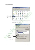
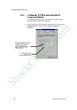
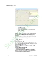
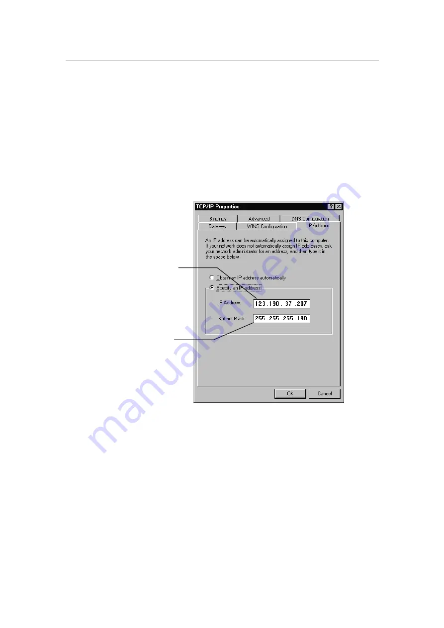
Select TCP/IP from the network component list and click on the 
Properties button.  The TCP/IP Properties dialog box is 
displayed. 


2.


Your Network Administrator may instruct you to obtain an IP 
address automatically by selecting the appropriate radio button. 

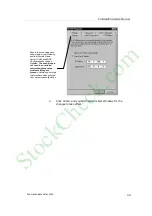
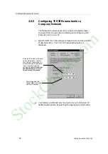
Enter the IP address to be used 
by this Workstation.  Contact 
your Network Administrator (or 
whoever assigns IP addresses 
in your network) to get the 
appropriate address. Note that 
each Workstation PC must 
have a unique IP address. 

Enter the appropriate 
Subnet Mask to be used 
with this IP address. 

StockCheck.com

Summary of Contents for ProStar 325 UV-Vis

Page 1: ...ProStar 325 UV Vis Variable Wavelength Detector Service Manual Installation Category II Pollution Degree 2 Safety Class 1 EN 61010 1 Publication Number 85 102009 00 S t o c k C h e c k c o m ...

Page 2: ...ProStar325 Service Manual 2 Publication date 8 May 2003 This page is intentionally left blank S t o c k C h e c k c o m ...

Page 3: ...18 633 118 Internet The Varian Internet home page can be found at http www varianinc com Varian Australia Pty Ltd is the owner of copyright on this document and any associated software Under law the written permission of Varian Australia Pty Ltd must be obtained before either the documentation or the software is copied reproduced translated or converted to electronic or other machine readable form...

Page 4: ... 3 Panels and covers 14 1 6 4 Other precautions 14 1 7 Service philosophy 15 1 7 1 Varian customer support policies 15 1 7 2 Service policy 15 1 7 3 Spare parts policy 15 1 7 4 Warranty 15 1 7 5 OEM Warranty 16 1 7 6 Contract maintenance 16 2 Pre Installation 17 2 1 Information symbols 17 2 1 1 Warnings and Cautions 17 2 2 Pre installation checklist 21 2 2 1 Pre installation complete 21 2 3 Weight...

Page 5: ...llation 33 3 5 1 Installation guide 33 3 6 Installation of Door Cap 34 3 7 Installation and Removal of Door 35 3 8 Software Installation 36 3 9 Ethernet connection 37 3 9 1 Networks 37 3 9 2 Where to Begin 38 3 9 3 Installing and Configuring the Ethernet Card in Your PC 39 3 9 4 Configuring TCP IP Parameters with No Company Network 41 3 9 5 Configuring TCP IP Parameters for a Company Network 43 3 ...

Page 6: ...ies 64 4 2 1 Low voltage power supplies 64 4 2 2 Deuterium D2 lamp power supply 65 4 2 3 Visible lamp power supply 66 4 3 Processor PWB 67 4 3 1 Processor PWB functions 67 4 3 2 Non Volatile Data Storage 70 4 3 3 Signal processing and A to D conversion 70 4 3 4 Relay Outputs 71 4 3 5 Peak Sensing 71 4 3 6 Analog Output 71 4 3 7 Calibration 73 4 3 8 Dual Wavelength 73 4 4 Initialization Sequence 74...

Page 7: ...3 2 Vis lamp source 92 5 3 3 Optics module 93 5 4 Installing Vis lamp option 96 5 4 1 Optimizing Vis lamp 99 5 5 Performance test 101 6 Spare parts 102 Location of major assemblies 102 6 1 Covers 102 6 2 Electronic spare parts 102 6 3 Optical spares parts 103 6 4 Upgrade kits 104 6 5 System cables 104 6 6 Miscellaneous 104 7 Diagnostics 105 7 1 Introduction 105 7 2 Power On Self Test POST 105 7 3 ...

Page 8: ...wnloading a method 112 7 8 4 Saving a method 113 7 9 Detector Status 113 7 9 1 Main 113 7 9 2 Internal Method 114 7 9 3 Logs 115 7 9 4 Alarms 115 7 10 Diagnostic Functions 116 7 10 1 Input Output 117 7 10 2 EEPROM 118 7 10 3 Mono Options 119 7 10 4 Gain and Dark Tables 121 7 10 5 Comms 123 7 11 Establishing communications 124 7 12 Calibration 125 7 12 1 Mono 125 7 12 2 0 Transmission 128 S t o c k...

Page 9: ...ProStar325 Service Manual Publication date 8 May 2003 9 S t o c k C h e c k c o m ...

Page 10: ...is manual The safety practices and hazards section described below is provided to help the user operate the detector safely Read these safety practices thoroughly before attempting to operate the detector and always operate the detector in accordance with these safety practices The detector system uses interlocks and covers which are designed to prevent inadvertent contact with any potential hazar...

Page 11: ...res Fundamentals of the ProStar 325 Safety practices and hazards Service philosophy 1 3 Design features Design features include High performance photodiode detectors Quartz over coated optics Deuterium arc ultraviolet source Tungsten halogen visible source with quartz window Double beam ratio recording Czery Turner monochromator Choice of four precision flowcell varieties Stackable module Simple l...

Page 12: ... an analog signal to an external chart recorder and or data collection system or as a digital signal to Star Workstation or Galaxie Wavelength absorbance parameters are time programmable on the standalone unit This manual instructs the user in the installation and operation of the 325 detector for non Workstation operation e g with the Pocket PC controller The detector s advanced optical design el...

Page 13: ...r re converted to analog The analog circuitry produces a voltage directly proportional to the ratio of the sample signal to the reference signal This voltage is supplied to the rear panel as the 1V AU integrator output and as a recorder output For extra flexibility the 325 detector can also be controlled via a hand held PPC You can use the PPC to download build and store methods from the host comp...

Page 14: ...ht Refractive index sensitivity Spectral bandwidth Autozero precision Cell length ratio Cell precision The results of all tests performed using the Verify package are automatically stored by the system in the software directory 1 6 Safety practices and hazards Information on safety practices appears throughout the documentation provided with your detector Before using the detector you must thoroug...

Page 15: ...es of the size and rating as stipulated in the text adjacent to the fuse holder at the rear of the detector or as specified in the manual Never use power cords with faulty or frayed insulation 1 6 2 Lamp source The UV and Vis lamps are enclosed in self contained modules Both operate at high temperatures and touching either of these may result in burns Before replacing a lamp that has been lit swit...

Page 16: ...em may involve materials solvents and solutions that are flammable corrosive toxic or otherwise hazardous Careless improper or unskilled use of such materials solvents and solutions can create explosion hazards fire hazards toxicity and other hazards which can result in death serious personal injury and damage to equipment and property ALWAYS ensure that laboratory safety practices governing the u...

Page 17: ...r wear and tear during their normal operation Examples include resistors inductors capacitors semi conductor devices relays lamps temperature probes detectors elements motors wiring board assemblies and the like General hardware for example sheet metal parts structural members assemblies and castings will normally outlast the useful life of the detector and therefore will only be supplied on an av...

Page 18: ...ems other PC accessories and OEM accessories used with the ProStar 325 are not covered by the Varian detector warranty Generally this type of equipment is sourced locally and therefore local supplier or vendor warrantees will apply 1 7 6 Contract maintenance After expiry of the warranty time service and or repair of Varian detectors and accessories are handled on a time and materials basis in acco...

Page 19: ...ProStar325 Service Manual Publication date 8 May 2003 19 S t o c k C h e c k c o m ...

Page 20: ...f the checklist to the Varian Sales and Service Office or local Varian agent dealing with the supply of the equipment On receipt of this document the Varian Sales and Service Office or local Varian agent will contact you and arrange a convenient time for installation 2 1 Information symbols 2 1 1 Warnings and Cautions Specific warnings and cautions appear in this manual which detail the hazard des...

Page 21: ... in the documentation or on the detector are Electrical shock Eye hazard Noxious gases Hot surfaces Fire hazard Sharp object Corrosive liquids Moving part Heavy weight danger to feet Heavy weight Part can be ejected danger to hands The following symbol may be used on warning labels attached to the detector When you see this symbol you must refer to the relevant operation or service manual for the ...

Page 22: ...ent Federal Communications Commission advisory The following is a Federal Communications Commission advisory Note This equipment has been tested and found to comply with the limits for a Class B digital device pursuant to part 15 of the FCC rules These limits are designed to provide reasonable protection against harmful interference in a residential installation This equipment generates uses and c...

Page 23: ...mmonly referred to as the LVD of the European Union Varian has confirmed that each product complies with the relevant Directives by testing a prototype against the prescribed EN European Norm standards Proof that a product complies with the Directives is indicated by the CE Marking appearing on the rear of the product the documentation package that accompanies the product containing a copy of the ...

Page 24: ...ll applicable preparations have been completed Please arrange for the installation to be completed I fully understand that charges may be levied if the installation by Varian Service personnel is delayed due to facilities not being prepared in accordance with the information contained in this manual Company name and address _____________________________________ ____________________________________...

Page 25: ...scarded Keep this manual for future reference Varian office card to be attached here 2 3 Weights and dimensions Warning Some of the packages are large and heavy To avoid the chance of injury to personnel or accidental damage to the equipment always use two or more people when handling the packages or lifting equipment into position Never attempt to lift the packages alone Detector weight System Un...

Page 26: ...esigned for operation in clean air conditions The laboratory must be free of all contaminants that could have a degrading effect on the detector s components Dust acid and organic vapors must be expelled from the work area The detector warranty will be void if the equipment is operated in substandard conditions Caution Operating specifications for the PC Monitor and Printer Plotters and other peri...

Page 27: ...und each unit in the system Remember to provide space for the computer monitor and printer The workbench should be about 90 cm 36 in high To avoid damage through spillage of the mobile phase solvents used and samples being analysed the worktops should be covered with a material that is corrosion resistant and impervious to liquids Allow sufficient bench space to permit installation of recorders wo...

Page 28: ...assembly For safety reasons a separate power outlet receptacle should be provided for each unit in the system Do not plan to use extension cords or outlet adaptors All ProStar 325 detectors are supplied with a 2metre 6 6 long power cord and three pin plug assembly that is compatible with common standards applicable in the local area Avoid using power supplies from a source that may be subject to e...

Page 29: ... Comm Ethernet TCP IP RJ 45 type connector system connection J14 Analog out female 9 pin D range connector J4 Relay out female 15 pin D range connector P9 Sync signals male 15 pin D range connector J10 Sync signals female 9 pin D range connector 2 9 Equipment on site 2 9 1 Insurance As the carrier s liability ceases when the equipment is delivered Varian recommends that the detector owner arrange ...

Page 30: ...ents Varian detectors are inherently robust and the packaging is designed to prevent internal damage However the contents form part of a precision measuring system and all packages should be handled with care In transit sharp jolts must be avoided and the packages should not be inverted or tilted unnecessarily Markings on the shipping cartons generally indicate which side of the package should be ...

Page 31: ... or compatible mouse Microsoft or compatible mouse Microsoft Windows 2000 including Service Pack 2 or later Windows NT service pack 6 or Windows XP Microsoft Windows 2000 including Service Pack 2 or later Windows NT service pack 6 or Windows XP Varian can supply a PC for the ProStar 325 in the recommended configuration Consult your local salesperson for details The operating system software will b...

Page 32: ...ctor may be used All network issues are to be dealt with by the users 2 10 3 Recommended printer plotter You can use any printer supported by your Microsoft Windows operating system The monitor keyboard printer plotter and detector are connected to the PC via cables that plug into the back of the PC Please consult your monitor and printer manuals for details of their individual cabling requirement...

Page 33: ...rify software installation and elementary performance tests will take around thirty minutes There is then a period of two hours that must be allowed for warm up before the detailed detector tests for conformance to specification can be carried out and during this time the CSR will demonstrate some of the basic system operating procedures If you will be installing the detector yourself you should u...

Page 34: ...ProStar325 Service Manual 34 Publication date 8 May 2003 S t o c k C h e c k c o m ...

Page 35: ...mer s responsibility to set up and maintain their own LAN Local Area Network Installation instructions for any ProStar accessory are given in the manuals accompanying those accessories The installation instructions in this publication are provided for the guidance of Customer Support Representatives CSRs who have completed the appropriate product training courses and are employed or otherwise auth...

Page 36: ...es and inform the customer of any necessary corrective action Postpone the installation until this is complete Note You should not attempt installation until the detector has been unpacked and placed on its intended workbench This is your customer s responsibility Warning The ProStar325 detector weighs approximately 15 5 kg To reduce the risk of injury to personnel two people should be used for li...

Page 37: ...r s responsibility A copy of the pre installation manual is in Section 2 Pre installation A removable sheet summarizes the state of site preparation The customer should return this sheet to your Sales and Service Office You should examine this sheet before committing to an installation date Record any irregularities and inform the customer of any necessary corrective action Postpone the installati...

Page 38: ...checklist is at the end of this chapter Make copies as required Packing list checked as consistent with order All items consistent with packing list Detector is unpacked and placed on its intended workbench by the customer as described in the Unpacking Instructions included in the packing crate All items checked as undamaged Suitable PC and printer configured correctly as described in the pre inst...

Page 39: ...ox All items checked as undamaged Installation section of the operation manual has been read for each accessory to determine the order in which they need to be installed depending on your software the accessory manuals may be on line and the accessories installed according to the instructions 3 6 Installation of Door Cap If the ProStar 325 is the top module in the stack the door cap should be inst...

Page 40: ...ProStar325 Service Manual 40 Publication date 8 May 2003 Figure 1 Door and Door Cap Orientation Magnetic door latch Adhesive side S t o c k C h e c k c o m ...

Page 41: ...ation and Removal of Door The module door may be attached to the front of the ProStar 325 to cover the tubing connections to the flowcell see below Figure 3 Door Installation Magnetic Latch Latch Plate Keep edge of door and door cap evenly flush on both sides Magnetic door latch S t o c k C h e c k c o m ...

Page 42: ...install the Star Workstation and Verify software All software is on a self loading CD that will automatically run when inserted into the CD ROM drive Follow the prompts to complete the installation Note you must be logged in as an Administrator or as a user with Administrator privileges to install the software Verify installation A quick reference guide to installing the Verify software is shown h...

Page 43: ...C that has no network interface you will need to install an Ethernet Network Interface Card PCI bus with a RJ 45 type connector The PC must have a spare PCI slot for the installation of this device Each detector will come pre configured with a unique MAC Media Access Control address You will be required to enable communications between the detector and pc and allocate IP addresses for each detecto...

Page 44: ...fer to this type of multi purpose network as a company network and a Network Administrator in your company will typically manage it If this is the case then follow the instructions for configuring your ProStar 325 Detector and Workstation for use on a company network The ProStar 325 Detector is provided with its IP address either by the Star Workstation or by software running on your network The s...

Page 45: ... Windows Before proceeding your Ethernet card should be recognized by Windows the appropriate driver has been loaded and can be configured from the Windows Control Panel When done the Network Neighborhood icon should appear on your Windows desktop NOTE For the following procedure the use of disks other than the ones that were used for the original Windows installation may result in an Ethernet dri...

Page 46: ...the following LAN Connection Properties dialog box is displayed Double click on the Network Connection icon to set your Network options otherwise click on the Install button If TCP IP is already listed in the list of network components skip to the Note after step 5 S t o c k C h e c k c o m ...

Page 47: ...etwork that is you are not assigning an IP address by a Network Administrator follow the next three steps If you are connecting your Workstation to a company network skip to Configuring TCP IP Parameters for a Company Network Select Protocol and click on the Add button Select Microsoft as the manufacturer Select TCP IP as the protocol Click OK The protocol is added to your installed network Compon...

Page 48: ...evious procedure 1 Select TCP IP from the network component list and click on the Properties button The TCP IP Properties dialog box is displayed Enter in an IP address Note that if you are adding more than one Workstation to this network each Workstation PC must have a unique IP address within this range The Subnet Mask will be automatically set Do not change this value S t o c k C h e c k c o m ...

Page 49: ... effect Ensure that no entries have been made in your Gateway and that Domain Name Server DNS and WINS Configuration have been disabled These entries are not used in an isolated network and may cause problems if they are present Delete any settings that may have been entered from a previous configuration S t o c k C h e c k c o m ...

Page 50: ...ck on the Properties button The TCP IP Properties dialog box is displayed 2 Your Network Administrator may instruct you to obtain an IP address automatically by selecting the appropriate radio button Enter the IP address to be used by this Workstation Contact your Network Administrator or whoever assigns IP addresses in your network to get the appropriate address Note that each Workstation PC must...

Page 51: ...ers in the Bindings and Advanced tabs 4 Click on OK in the Network dialog box You will need to reboot Windows for the changes to take affect Contact your Network Administrator to see what the appropriate settings are for your Gateway and whether Domain Name Server DNS and WINS Configuration are needed S t o c k C h e c k c o m ...

Page 52: ... and the TCP IP host will be locked out from controlling the detector There will be a status message in the software indicating the state of the IrDA host control The hand held pc can control multiple detectors without conflict This is made possible because each detector has a unique IP address Simply point it at the detector to establish communication It needs to be line of sight and has a workin...

Page 53: ...sted pair Ethernet crossover cable Category 5 or better J10 Sync signals female 9 pin D range connector used with synchronization signal cables P9 Sync signals male 15 pin D range connector used with synchronization signal cables J4 Relay out female 15 pin D range connector used to control the four programmable external event relays and peak sense relay J14 Analog out female 9 pin D range connecto...

Page 54: ... states and transitions Pin Designations for P9 and J10 An input is activated or said to be present when its two signal wires are connected together This is quite often done with a relay contact closure If the inputs are driven from another instrument with optical isolators or other polarized devices then attention must be paid to the polarity of the signal wire connections The positive output sig...

Page 55: ...ogram Start In This polarized edge triggered input signal will start the active method if the ProStar 325 is in the READY state Start Out This polarized output signal will be activated for 600 milliseconds when the ProStar 325 starts a time program Fault In This polarized edge triggered input signal informs the ProStar 325 that a fault condition exists in another instrument in the system The ProSt...

Page 56: ...ing the instrument to the power supply ensure that both the instrument and the power supply are turned off the power switch is pressed The power switch is a rocker type switch located on the front panel that connects directly to the power receptacle on the rear panel Press l for on for off Note Do not connect the instrument to the mains power supply until you have made sure that the two line fuses...

Page 57: ...voltage rating y volts This code must correspond to the code appearing next to the fuse holders Note Always check the information printed on the rear of the detector for the most up to date details regarding the fuse type For details on checking and replacing fuses see Electronics section 3 17 Power Up After connecting the detector to AC power press l on the power rocker switch The detector will s...

Page 58: ...nd on the current state and a number of signals specifically SYNC signals and or a number of internal events which can also cause state transitions NOT READY LAMP OFF Detector is not ready for a run but is useable It will be in this state after POWER UP or when all lamps are turned off or after a fatal fault is received and the option is to turn lamps off after fault It will not leave this state u...

Page 59: ... data is collected the detector will calculate relevant Peak Sense control information READY Detector is now useable Once the detector receives a START IN or command Start it will progress to RUNNING state RUNNING Method is currently being run and the method clock is on STOPPED Method clock has been stopped and the run method can be restarted through START IN or method Start command DIAGNOSTIC Thi...

Page 60: ...el detect level ignore detect transiti on detect transiti on RUNNING active not active Pulse on entry armed Pulse Ignore ignore ignore ignore detect transiti on STOPPED active not active not active armed Pulse detect level ignore ignore detect transiti on detect transiti on DIAGNOSTI C settab le settab le settab le settab le monitor monito r monito r monitor monitor 3 20 Instrument performance tes...

Page 61: ... problem To start the installation tests using the Verify software Click on the Windows Start button Point to Programs and select ProStar325 from the flyout menu Select the Verify application from the second flyout menu After the initial ProStar flash screen appears the Verify application will open Select Tests and then select the Instrument Performance Tests radio button The verify software will ...

Page 62: ...stored in the ProStar directory and saved with the following format DATE TIME RVO For example 16 Apr 97 3 57 48 PM RVO The date and time will appear in the same form that is set in the Windows Regional Settings Properties dialog box that is accessed from the Windows Control Panel This feature will aid in keeping a history of the instrument s performance Print two copies of the Reports page One cop...

Page 63: ...OWCELL 4x0 15 SUPER PREP 15ul 02 101821 00 FLOWCELL 4x0 SEMI MICRO 1 6ul All flowcells can be removed and re installed as follows The flowcell should be removed with the connecting tubing fitted These must be removed outside the detector compartment Access the flowcell compartment by removing the green front door Remove the flat panel by loosening the single screw on the top left hand corner Loose...

Page 64: ...n Used on all types except 4x0 15 16 101265 00 Fitting 1 16 tube nut ferrule flat bottom Pack of 10 Used on flowcell 4x0 15 only 16 101269 00 16 101264 00 Fitting 1 8 tube nut flat bottom each Fitting 1 8 tube ferrule Pack of 10 The flowcells are constructed from titanium and are provided with quartz optics windows Tubing connections are PEEK type except for the Super Prep flowcell which uses TEFZ...

Page 65: ...ay 2003 65 Fit the nuts and ferrules on the peek tube as shown below Screw these two tubes into the body of the flowcell Do not over tighten as this will damage the threads Each flowcell has an inlet and outlet connection S t o c k C h e c k c o m ...

Page 66: ...ess Cover the flowcell opening with a piece of 3 x 5 card or always place a flowcell in the flowcell opening 3 21 3 Cleaning the flowcell The high sensitivity of the detector and the low volume of the flowcell make it imperative that a high standard of solvent purity and general system cleanliness be maintained A contaminated flowcell can lead to noise and drift problems that are often mistakenly ...

Page 67: ...king or breaking solvent line fittings care should be taken to prevent any contamination of exposed fittings Tubing should be sealed or capped when not actually connected Thread lubricants should never be applied to compression fittings The external windows of the flowcell can be cleaned with a dry clean source of compressed air or nitrogen Remove the flowcell and carefully blow any dust or contam...

Page 68: ... an unstable baseline Note the arrow stamped on the restrictor body which must point away from the flowcell outlet port and toward the waste receiver The threaded plastic fittings should be finger tightened only enough to prevent leaks Some 1 16 tubing is supplied at both the inlet and outlet of the restrictor The inlet tubing is provided with a 1 16 plastic fitting for connecting to the flowcell ...

Page 69: ...how to change both the Visible and UV lamps in the detector are included in the Optics section of this manual A new UV replacement lamp is delivered tested and pre aligned on a mounting bracket It is designed for direct exchange installation and requires no alignment after it has been installed Follow the steps given in the Optics section of this manual for removal of the old lamp and installation...

Page 70: ...o column in the system Set the detector wavelength to 240 nm and a time constant of two seconds Adjust the recorder attenuation to 0 001 AUFS Record 10 to 15 minutes of detector output at a chart speed of 1cm min Now stop the pump and continue to record detector output NOTE It may be necessary to autozero initially to keep the trace on the chart paper If the noise and or drift problem disappears a...

Page 71: ...ProStar325 Service Manual Publication date 8 May 2003 71 S t o c k C h e c k c o m ...

Page 72: ...ProStar325 Service Manual 72 Publication date 8 May 2003 S t o c k C h e c k c o m ...

Page 73: ...ignals including accessory signals are also handled by this PWB Mains supply for the instrument enters through a Corcom filter network and varistor combination which help to suppress transient disturbances Overcurrent protection fuses 1FS1 and 1FS2 are mounted on the rear panel The fuses are T3 15AH250V and are contained in the input module The two OEM supplies are universal mains switchmode suppl...

Page 74: ...rce transistor Q8 turns on and tries to sink 300mA This places 475V across the lamp via R194 and R241 The lamp starts conducting and is carried into the negative resistance region by the current from C226 The voltage on the anode drops below the voltage on D14 anode and the current starts to flow from the run supply The current builds up to 300mA and the current source starts to regulate causing t...

Page 75: ... the D2 supply voltage is exposed Contact with this voltage may cause electric shock or death Minimize this risk by keeping the cover in place The following is the sequence of events when the D2 lamp striking Start Set the current to the filament Wait 10seconds Is the filament on Strike lamp and wait 0 5seconds Has the lamp struck Disable filament and strike controls No N Yes Yes S t o c k C h e c...

Page 76: ...ed to report that filament current is flowing lamp lit 4 3 Processor PWB The Processor PWB contains all necessary photometric signal processing and I O devices to control the instrument and any accessories Operating conditions and results are transferred between the instrument and host computer by an Ethernet TCP IP interface The computer has ultimate control over the system and is responsible for...

Page 77: ...field upgradeable flash memory Also on board is 128MB of SDRAM Software contained in the flash memory gives the microprocessor multitasking capabilities which enable a number of operations to be carried out simultaneously A thumbwheel switch and two seven segment displays are provided for diagnostic control and reporting These tasks are executed by the processor PWB Wavelength drive Photometric si...

Page 78: ...ith this data transmission protocol through the Microcontroller IC U1 The microcontroller has a 3 3V PCI bus interface which is compatible with the 3 3V I O from the Ethernet Controller chip 4 3 1 3 JTAG port The Processor PWB is equipped with a JTAG accessible through connector P5 It serially connects the Microcontroller CPU and FPGA This gives any device connected to the port access to all the d...

Page 79: ... Xilinx It is direct drive with current controlled microstepping and provides accuracy of 1nm Lamp control and reporting source lamp supplies are turned on or off by the Xilinx according to user requirements A logic low on either the D2 ON or VIS ON signals enables the respective supply although the D2 lamp also requires a warm up period prior to striking hence the need for the D2 WARM UP signal V...

Page 80: ...ropriate test through the diagnostics thumbwheel selector switch refer this chapter and Diagnostics 4 3 3 Signal processing and A to D conversion Output signals from the Dual Photodiode Pre amp PWB are fed into the ANALOG INPUT circuitry This circuit then performs a number of functions Multiplexing between the two channels buffering level shifting amplification The signals are then sampled and hel...

Page 81: ...on the data in real time The purpose of the peak sensing function is to control a fraction collector via the peak sensing relay The peak sensing functions will trigger the following events The start or end of a peak A valley point These events will either trigger the peak sense relay directly or start a time slice function depending on the current method definition It will also mark the selected a...

Page 82: ...l occur only after the time interval of the peak sense duration parameter The analog output is driven by a 16 bit converter with an output range of 0 1V FS with 11 20 over range This gives an analog output resolution at 1AU Volt 1V 131 65535 20uV 20uAU The Full Scale ranges are Full Scale AU Resolution uAU 0 0005 0 01 0 001 0 02 0 002 0 04 0 005 0 1 0 01 0 2 0 02 0 4 0 05 1 0 0 1 2 0 0 2 4 0 0 5 1...

Page 83: ...ion for more details 4 3 7 2 Wavelength Calibration When the detector receives a command to calibrate the wavelength it goes through the following sequence of events Switch on the D2 lamp Scan and find zero order and 656 1nm peak Calibrate the wavelength with a linear calibration from zero through to 656 1nm Store the calibration into EEPROM In any event of failure to complete the calibration the ...

Page 84: ...sition of the diagnostic rotary switch and perform the test Perform normal start up checks Perform power supply check Activate READY_OUT SYNC signal 4 5 LEDs and diagnostic display The Processor PWB is fitted with various LEDs to indicate functions and provide diagnostic information to CSRs Under normal circumstances four green LEDs should be lit LED5 5V OK LED6 9V OK LED7 9V OK LED8 24V OK CPU re...

Page 85: ...through all SDRAM Display 20 if OK Display 22 if ERROR 3 ADC DAC test Continuously checks the main ADC operation 4 ACCESSORY OUTPUT test Checks all SYNC and relay outputs by toggling in a two second period Display 40 during this test 5 Not used at present 6 MONOCHROMATOR MOTOR test Initializes the stepper motor and sets the monochromator to somewhere near theoretical zero order It then continuousl...

Page 86: ...in program in the flash memory Displays 00 if OK Displays 01 if ERROR 12 Not used at present 13 Not used at present 14 Not used at present 15 Not used at present 4 7 Dual Photodiode pre amp PWB The Preamplifier PWB takes the small diode currents supplied from the photodiode detectors and converts them to a useable signal voltage The cable from the Processor PWB is a shielded twisted pair type used...

Page 87: ...controlled by signals from the FPGA Led Status Color Power Initializing Power On Yellow flashing Green Lamp Lamp On Fault Green Red Ready Run Not Ready Ready Stopped Method Running Off Green Yellow 4 9 Removal replacement procedures 4 9 1 Processor PWB Switch off detector and unplug mains cable Removal Remove the detector s top main cover which is held by two screws on each side Remove the two scr...

Page 88: ...Service Manual 88 Publication date 8 May 2003 Locate and remove the two screws at the rear of the detector used to secure the fan baffle Then swing the baffle to the right as shown screws S t o c k C h e c k c o m ...

Page 89: ...ection of this manual Remove the earth lug screw located on the Processor PWB Remove the single screw holding down the power supply module This is located on the outer edge of the detector adjacent to the power supply module Disengage the safety cover and slide the power supply module toward the front of the detector At this stage the S t o c k C h e c k c o m ...

Page 90: ...lly held it in place The Processor PWB will now be exposed Disconnect all cables from the Processor PWB The PWB can now be removed along with its mounting bracket Replacement When a new replacement Processor PWB is received it will be accompanied by two labels MAC address Detector serial number These labels need to be stuck over the existing ones located on the rear panel of the detector as shown ...

Page 91: ...e Diagnostics section for details 4 9 2 Dual Photodiode PWB Remove the Optics module as described in the Optics section of this manual Remove the two hexaganol head type screws which fasten the photodiode PWB This will enable removal of the PWB Note Whenever this PWB is replaced you are required to perform a wavelength 0 T calibration Refer to the Diagnostics section for details Dual Photodiodes P...

Page 92: ... as you face the detector Disconnect the ribbon cable to this PWB Locate and remove the two screws holding the PWB and its mounting bracket The PWB can now be removed 4 9 4 Power Supplies Remove the main detector cover Remove the single screw holding down the power supply module This is found on the outer edge of the detector adjacent to the power supply module S t o c k C h e c k c o m ...

Page 93: ...es it is important when replacing the fan that the orientation is correct The air flow must enter the detector through the rear and flow through the fan baffles There is an arrow marked on the fan which must point towards the front of the detector 4 9 6 Fuses The ProStar325 contains two fuses which are located at the back of the instrument To replace a fuse disconnect the detector from the power s...

Page 94: ...se holder 4 Check that the fuses are the correct type and are not damaged If necessary replace them 5 Place the fuses into the red fuse holder push the holder back into the mains input connector and then lower the cap 6 Reconnect the instrument to the mains power supply WARNING FIRE HAZARD To avoid fire hazard replace fuses ONLY with fuses of the same rating and type Always switch off the AC power...

Page 95: ...ProStar325 Service Manual Publication date 8 May 2003 95 Slide the fuse compartment out The two fuses are located on either side of the compartment S t o c k C h e c k c o m ...

Page 96: ...vide an output for measurement by the electronics system It is not possible to perform any optical alignment or replace any optical components within the ProStar 325 The optics module is designed to be replaced as a complete assembly 5 2 Optics module The optics module contains the UV and Vis source lamps source optics beam splitter entrance exit masks monochromator and mirror assemblies that form...

Page 97: ... sealed unit that supplies a single wavelength beam of light directed through the flowcell and conforms within 1nm to a specifically selected wavelength The entrance mask produces a defined beam of polychromatic UV and visible light before it gets collimated by the first collimating mirror The beam is then directed onto a holographic grating that disperses it into a continuous spectrum A stepper m...

Page 98: ... grating The dispersed light then hits the exit collimating mirror before leaving the monochromator through the exit mask From here the beams are passed onto the dual photo diode detectors Exit and entrance masks The masks used throughout the optical system determine the optical resolution of the detector They have a nominal spectral bandwidth of 6nm Beam splitter The beam splitter is a silica pla...

Page 99: ...ProStar325 Service Manual Publication date 8 May 2003 99 Deuteriu m lamp S t o c k C h e c k c o m ...

Page 100: ...ProStar325 Service Manual 100 Publication date 8 May 2003 Deuterium lamp optical path Visible lamp optical path S t o c k C h e c k c o m ...

Page 101: ...ng the glass envelope of either the UV or Visible lamp will reduce its efficiency Never touch the glass surfaces of new lamps Aways handle a lamp by its base or use a tissue or cloth Warning Hazardous UV radiation is emitted by the UV lamp This radiation can cause serious damage to human eyes Never operate a UV lamp outside of its correct position in the lamp turret 5 3 1 UV lamp source Removal Re...

Page 102: ...rvice Manual 102 Publication date 8 May 2003 Loosen the two thumbscrews located at the front Holding the lamp module by these thumbscrews carefully pull out the assembly latch push upwards S t o c k C h e c k c o m ...

Page 103: ... the two thumbscrews Re connect the three way connector Engage the safety latch by sliding it back down 5 3 2 Vis lamp source Removal Remove the front green door which will expose a flat panel Remove this flat panel by loosening the holding screw on the top left hand corner Locate the Vis lamp housing Loosen the thumbscrew and carefully remove the housing thumbscrew S t o c k C h e c k c o m ...

Page 104: ...ith a cloth slide the two pins on the Vis lamp into the connector terminals as far in as possible Replace the lamp housing and tighten the thumbscrew Note Once this is complete check that the new Vis lamp is not causing any over range errors Please refer to Diagnostics section page 120 When handling the new lamp assembly DO NOT TOUCH the lamp glass oil from your fingers will permanently etch onto ...

Page 105: ...It is held by two screws on each side Slide the detector forward on a bench to enable access to three locating holes underneath These are found towards the front of the detector Using a 4mm nut driver remove the three screws and washers found in these locating holes These are holding the optics module to the main detector chassis Once removed slide the detector back fully onto the bench With the d...

Page 106: ...efully lift the optics module out of the detector and place safely on a flat bench Remove the two screws on the large silver clamp that secures the black foam padding around the optics module Take off all the padding pieces to expose the monochromator This also enables access for replacing the Dual Photodiodes Detector PWB S t o c k C h e c k c o m ...

Page 107: ...e 8 May 2003 107 5 4 Installing Vis lamp option The Vis lamp upgrade kit 01 107439 00 will consist of the following parts Vis lamp and housing Panel cover 2 x spacers 2 x M4 hex cap screws 2 x spring washes 2 x washes S t o c k C h e c k c o m ...

Page 108: ... Publication date 8 May 2003 Vis lamp upgrade kit Remove the detector s top main cover which is held by two screws on each side Remove the two screws securing the small side panel and lower it down remove S t o c k C h e c k c o m ...

Page 109: ... and remove the two screws at the rear of the detector used to secure the fan baffle Then swing the baffle to the right Remove the two screws securing the small plate adjacent to the UV lamp source These three items can be discarded screw s S t o c k C h e c k c o m ...

Page 110: ...g pieces as shown below and fit the two spacers provided in the upgrade kit over the exposed screw holes Fit the Vis lamp housing on top of the spacers and fit the two hex cap screws that come with the upgrade kit Leave the screws Remove these two pieces S t o c k C h e c k c o m ...

Page 111: ...o its original position Note Whenever the Vis lamp option is installed you are required to perform a 0 T calibration as described in the Diagnostics section Do this after you have optimized the Vis lamp as described below 5 4 1 Optimizing Vis lamp To optimize the light throughput of the Vis lamp you will need to connect the ProStar325 detector to a local PC establish communication and open the Dia...

Page 112: ...e and set Method End Action to Reset Select Download Method and wait for the Start button to become active Press Start Enter the Main page to view the signal trace on the screen Move the Vis lamp housing with your fingers to increase the signal level on the screen When the maximum level has been achieved tighten the two screws evenly The signal level may go down slightly when you do this Try to mi...

Page 113: ...ing any over range errors Please refer to Diagnostics section page 120 5 5 Performance test Execute the instrument performance install tests to check that the instrument meets specification 1 Switch on the PC and load the Verify software 2 Click on the Tests tab 3 Click Start to begin the tests The software will start the instrument performance tests required to verify the instrument meets specifi...

Page 114: ...date 8 May 2003 The following tests are automatically enabled Noise test Wavelength Accuracy D2 emission only Wavelength Reproducibility SBW Accuracy Auto Precision Detector Linearity Refractive Index Cell Length Ratio S t o c k C h e c k c o m ...

Page 115: ...ER LC DETECTOR BASE 01 107218 00 ASSY CASTING LC DETECTOR FRONT 01 107288 00 ASSY DOOR 09 102066 00 CAP DOOR ASSY 01 107146 00 ASSY FLOWCELL SURROUND 6 2 Electronic spare parts PWB s Part Number Description 02 101797 90 ASSY PWB FRONT PANEL LED IrDA 02 101759 90 ASSY PWB INSTRUMENT PROCESSOR 02 101842 90 ASSY PWB DUAL PHOTODIODE PRE AMP 02 101865 90 ASSY PWB 325 REAR PANEL INTERFACE 02 101875 90 A...

Page 116: ...79 100447 00 ASSY POWER SUPPLY 5V 12V 79 100448 00 ASSY POWER SUPPLY 24V 01 107192 90 ASSY FAN 48 100359 00 SWITCH MAINS 12 101313 90 ASSY CORCOM MAINS FILTER 6 3 Optical spares parts ASSEMBLIES Part Number Description 01 107203 90 ASSY OPTICS COMPLETE LC DETECTOR LAMPS Part Number Description 01 107154 00 ASSY D2 LAMP MODULE PRE ALIGNED 56 101365 00 LAMP MINIATURE QUARTZ HALOGEN FLOWCELLS Part Nu...

Page 117: ...escription 01 107234 00 ETHERNET CROSSOVER LC to PC 01 107233 00 ETHERNET CABLE network configuration 6 6 Miscellaneous Part Number Description 01 107433 00 ASSY BACK PRESSURE REGULATOR 16 101265 00 FITTING 1 8 TUBE NUT FERRULE FLAT BOTTOM Pack of 10 16 101269 00 FITTING 1 8 TUBE NUT FLAT BOTTOM each 16 101264 00 FITTING 1 8 TUBE FERRULE Pack of 10 85 102015 00 PROSTAR 325 SOFTWARE CD 85 102016 00...

Page 118: ...ProStar325 Service Manual 118 Publication date 8 May 2003 S t o c k C h e c k c o m ...

Page 119: ...d by firmware in conjunction with a 15 position thumbwheel selector switch on the main PWB A service diagnostics program Diagnostics exe 7 2 Power On Self Test POST Diagnostics switch position 0 These are performed when the detector is switched on during normal operation Position 0 is reserved for normal operation This allows for the normal start up sequence executed from the boot block to take pl...

Page 120: ...H MEMORY CRC CHECKSUM BOOT BLOCK test The instrument continuously tests the boot block program A 10 will be displayed on the seven segment LED s if every test has succeeded and a 11 will be displayed continuously if any test has failed although testing will continue Note that this Flash Memory test would be done immediately after a reset Diagnostics switch position 2 RAM test The instrument contin...

Page 121: ...ion 7 Deuterium lamp test Enable the lamp filament and display 76 on the seven segment LED s up to and including the warm up period Then switch on the lamp and display 70 while it is operating Diagnostics switch position 8 QI VIS lamp test If fitted i e VIS_FITTED detected the visible lamp will be enabled If not fitted the test shall do nothing Display a 86 on the seven segment LED s prior to lamp...

Page 122: ... service diagnostics program for the ProStar 325 detector you will need to insert the Verify CD into a computer CD ROM drive and connect the pc to the detector via the Ethernet connection From the Windows task bar select Start Run Browse On the CD find the file Service Diagnostics Diagnostics exe This will execute the LCDiagnostics Application which you can use to verify all working aspects of the...

Page 123: ...mation into the EEPROM such as detector installation date lamp installation date lamp serial number detector serial number customer details 7 6 3 Menu task bars The top menu bar allows for file management tasks editing options graph trace options mathematics calculations execution of system commands Help files The second menu bar is common to all pages The extreme corners display the X Y co ordina...

Page 124: ...tus description section of this manual 7 7 Main Display The Main page is used to view spectrum traces collected during troubleshooting and detector performance verification X Y axis co ordinates are chosen in the Method page The trace window can be expanded to any size by dragging out its edges Double clicking in the trace window will also toggle the size of the window making it possible to view r...

Page 125: ...Method Editor page is used for building methods There are two modes of operation possible on this page Editing Viewing The active mode is shown at the top of the parameters box Double clicking in either of these two windows will expand it to full screen viewing S t o c k C h e c k c o m ...

Page 126: ...n the Lines column and is specified in minutes There is a basic default method stored in each detector with a single command line beginning at time 0 00 This line cannot be modified nor deleted To add a line to a method select the Add Line button You will now activate the Editing mode function and the top of the parameter s window will indicate this accordingly This will enable all entry fields in...

Page 127: ...nd line in the method has an End of Method instruction assigned to it a dialog pop up box will appear on the computer screen prompting for one to be assigned when the Download Method button is pressed When finished selecting parameters click OK 7 8 2 Modifying a method To edit an existing method highlight the desired command line and click on the Edit Line button This will bring you into Editing m...

Page 128: ...A method can be saved using the top menu bar by clicking on File Save Methods As From here you can allocate a method file name and store it in the desired location 7 9 Detector Status Entering this page will display a further four sub pages located within S t o c k C h e c k c o m ...

Page 129: ...t buttons to perform these functions Instrument Details details such as name and model of the connected detector will be displayed here Instrument Status this will display the current status of the connected detector and indicate the state of the source lamps These are individually color coded and each color is defined below Instrument Status Color Not ready Ready Running Offline Red Green Lime gr...

Page 130: ...will also be used This page will display the default parameters used in this method It is not possible to modify it from this page If you wish to modify click on the Modify button which will then put you in editing mode and allow you to change the parameters in the Method page as described previously 7 9 3 Logs These logs give an account of detector performed functions reported errors This can be ...

Page 131: ...Alarms The alarms page allows you to program either source lamp to switch on and off at specified times This is useful in turning the lamps on prior to using the detector and allowing them adequate time to warm up and stabilize It uses the internal clock of the detector as its reference 7 10 Diagnostic Functions Entering this Diagnostics page will display a further eight sub pages located within M...

Page 132: ...me active Analog Supply Voltages Used to view power supply voltage levels coming from the two rear power supplies PS1 PS2 These measurements are performed by the ADC circuits on the main Processor PWB Analog In Verify the Analog input and output circuits DACA DACB by setting the sliders on the two Analog Out controls to any value and then have this voltage measured and displayed in the correspondi...

Page 133: ... on the D range connector pin or on the Rear Panel Interface PWB if fitted The five detector relays can be individually toggled to verify their operation as well as checking the bi color status of each of the three front panel LED s 7 10 2 EEPROM Use this page to view and reset the information contents of the EEPROM From here you can reset the dates and operating hours whenever installing a new la...

Page 134: ... wavelengths caused by mechanical errors such as grating squareness The D2 emission line at 656 1nm is a strong signal and is well characterized It is widely used in UV Vis spectroscopy as an accurate wavelength marker The detector performs a search for this emission line and then does a search for 0nm A correction factor is then applied between these two points This will ensure that these two poi...

Page 135: ...EEPROM Refer to the Calibration section below Wavescan Parameters enter parameters here to perform wavelength scans A typical scan of the D2 lines can be set up to verify performance of the detector Mono Movement drives the monochromator grating motor to verify its operation You can slew the motor to a specific wavelength and also check the bi polar micro stepping function Clicking goto zero will ...

Page 136: ...talled Vis lamp can cause the detector to over range at around 730nm This can occur with high throughput detectors using a brighter than normal Vis lamp If you experience this over range after a new Vis lamp has been fitted then it is suggested to move the lamp from its current position by moving it either sideways or in out of its mount This problem will only be highlighted when scanning in singl...

Page 137: ...range should be quite low because the signal strength is high Above this range the gain stages should increase as the signal level decreases Around 656nm the gain should decrease again in the presence of the deuterium peak at 656 1nm All this should be reflected in the gain table data If the gain stages are all high across the entire range then this will indicate that a low or possibly no signal i...

Page 138: ... of the 15 gain stages is selected and any offset voltage present in the signal processing circuits is measured and tabled against its corresponding gain Then when the detector is in its normal operating mode these offset values are subtracted from the signal level to give a true indication of actual signal strength These measurements are displayed in ADC counts and both channels should be overlap...

Page 139: ...ProStar325 Service Manual Publication date 8 May 2003 139 Reference Dark Measurements 1 2 3 4 5 6 7 8 9 10 11 12 13 14 15 Gain Stages ADC Counts 7 10 5 Comms S t o c k C h e c k c o m ...

Page 140: ... assign an IP address subnet gateway settings Enter the details in the desired fields then click Set These details can also be uploaded from the detector by clicking on Load TCP IP Connection If you know the unique IP address of the detector you wish to connect to enter in the address and click connect This is a direct method of connection and is an alternative to using the Discover method as prev...

Page 141: ...at workstation either directly or via a network setup Highlight the desired detector and click on connect Once communications has been established the Not Ready Lamp off indicator will turn a red color This means the detector has connected to the P C and is ready for the D2 lamp to be turned on In some instances the D2 lamp may be already on therefore the indicator will be a green color S t o c k ...

Page 142: ...replacing the optics module Wavelength accuracy test fails After replacing the main Processor PWB After replacing the Detector PWB Establish communications with the detector as described above Turn the D2 Lamp ON by clicking the D2 Lamp button and wait until it is ready Both the Ready and D2 Lamp is ON indicators should be a green color S t o c k C h e c k c o m ...

Page 143: ...Publication date 8 May 2003 143 Go to Diagnostic Main and tick Enter Diagnostic State as shown below You must be in data collect mode Note you must select this mode before enabling the Diagnostic State S t o c k C h e c k c o m ...

Page 144: ...ptions and make sure that the detector is in the Diagnostic state check the bottom of the screen and observe that there is a violet box next to the Diagnostic sign Click on calibrate and a pop up box Starting Mono Calibration will appear Press OK S t o c k C h e c k c o m ...

Page 145: ...n is in progress Once completed the Mono Calibration completed pop up box will appear Press OK The wavelength calibration is now complete Go back to Main tab and un tick Enter Diagnostic State 7 12 2 0 Transmission There are three 0 T calibration options available Calibrate with Vis lamp on S t o c k C h e c k c o m ...

Page 146: ... if Vis fitted Y if Vis fitted Replacing Processor PWB if Vis fitted Y if Vis fitted Replacing Detector PWB if Vis fitted Y if Vis fitted Replacing mono if Vis fitted Y if Vis fitted Refractive Index test fails if Vis fitted Y if Vis fitted Detector Linearity test fails if Vis fitted Y if Vis fitted Establish communications as described in the procedure above Turn the D2 Lamp ON by clicking the D2...

Page 147: ...ation option required as per the table above The Starting 0 T Calibration now pop up box will appear Click OK The following information boxes will appear Place a black piece of paper between the Flow Cell and the Surround This will block the bottom light path Click OK Make sure you have only blocked the sample beam S t o c k C h e c k c o m ...

Page 148: ...h will appear indicating that calibration is in progress When the following pop up box appears remove the black piece of paper and click OK Another pop up box will appear indicating that calibration is complete Click OK to finish 0 T calibration S t o c k C h e c k c o m ...

Page 149: ...ProStar325 Service Manual Publication date 8 May 2003 149 S t o c k C h e c k c o m ...

Reviews: