Section 8
—
Setup Menu
MCP-25/MS
Valco Cincinnati
8-9
MC051 (July 2002)
F1
Marking-Valve
Configuration
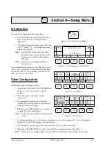
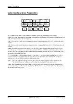
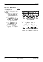
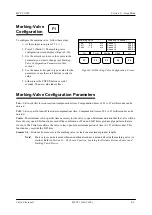
To configure the marking valve, follow these steps:
1. At the setup screen, press F5 (>>>).
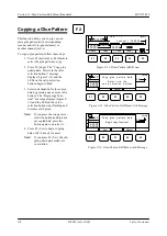
2. Press F1 (Mark.V). The marking-valve
configuration screen displays (Figure 8-10).
3. Use the arrow keys to move the cursor to the
parameter you want to change (see
Marking-
Valve Configuration Parameters
in this
section).
4. Use the numeric keypad to type a value for the
parameter, or use the scroll buttons to select a
value.
5. Either press the ENTER button or wait 3
seconds. The new value takes effect.
Marking-Valve Configuration Parameters
Ton
—Valve-specific turn-on reaction (compensation) time. Compensation times of 0.1 to 25 milliseconds can be
entered.
Toff
—Valve-specific turn-off reaction (compensation) time. Compensation times of 0.1 to 25 milliseconds can be
entered.
Tmin
—The minimum valve-specific time necessary for the valve to open. Minimum duration that the valve will be
forced to stay open. This function is used if the combination of Ton and Toff times produce glue patterns that are
too short. The Tmin time allows the valve to stay open for a minimum period of time (0.1-25 milliseconds). This
function may override the Toff time.
Sensors 1-4
—Distance from sensors to the marking valve (at least one maximum product length)
Note!
These values can be learned when an additional scanner is mounted beside the marking valve (or
ejector). Refer to
Section 13
—
The Learn Function,
Learning the Distance Between Sensor and
Marking Valve/Ejector
.
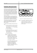
Figure 8-10. Marking-Valve Configuration Screen
Tol
Form
Section
Clock
Ton
4.0
ms
Toff
4.0
ms
Tmin
1.5
ms
>>>
F1
F2
F3
F4
F5
Marking valve
1
Distance to sensor
Sensor 1
000.00
Sensor 2
000.00
Sensor 3
000.00
Sensor 4
000.00
Summary of Contents for MCP-25/MS
Page 1: ...MCP 25 MS Control Manual Number MC051 Release Date June 2004 ...
Page 25: ......
Page 27: ......
Page 28: ......
Page 29: ...3 4 5 1 2 2 4 5 3 1 ...
Page 30: ......
Page 31: ......
Page 33: ...4 8 12 11 10 9 6 7 5 3 2 1 ...
Page 34: ...3 7 9 10 8 5 6 4 1 2 1 4 3 2 ...
Page 35: ...1 3 4 2 ...
Page 36: ...7 9 10 8 3 5 6 4 1 2 ...
Page 37: ...SHD NPN 5 4 3 24V Low Level Detector 0V 1 2 ...
Page 38: ......
Page 39: ......
Page 40: ......
Page 41: ......
Page 42: ......
Page 43: ...3 4 5 6 2 3 1 5 6 4 1 2 ...
Page 44: ......
Page 45: ......
Page 46: ......
Page 47: ......
Page 48: ......
Page 49: ...RODUCT 7 10 9 8 3 5 6 4 1 2 8 10 9 2 5 7 6 3 4 1 ...
Page 50: ......
Page 51: ......
Page 52: ...6 8 10 9 7 1 3 5 4 2 ...
Page 53: ......
Page 54: ......
Page 55: ...6 8 10 9 7 1 3 5 4 2 ...
Page 56: ...VA LC O CI NCIN NA TI INC 513 87 4 6550 5 13 87 4 6550 VALC O C INCIN NATI INC ...
Page 57: ......
Page 58: ......
Page 59: ......
Page 60: ......
Page 61: ......
Page 62: ......
Page 87: ......
Page 99: ...F1 F2 F3 F4 F5 ...

