background image

Section 8

Setup Menu

MCP-25/MS


 Valco Cincinnati

8-6

MC051 (July 2002)

Encoder Configuration

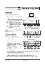
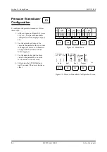
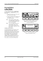
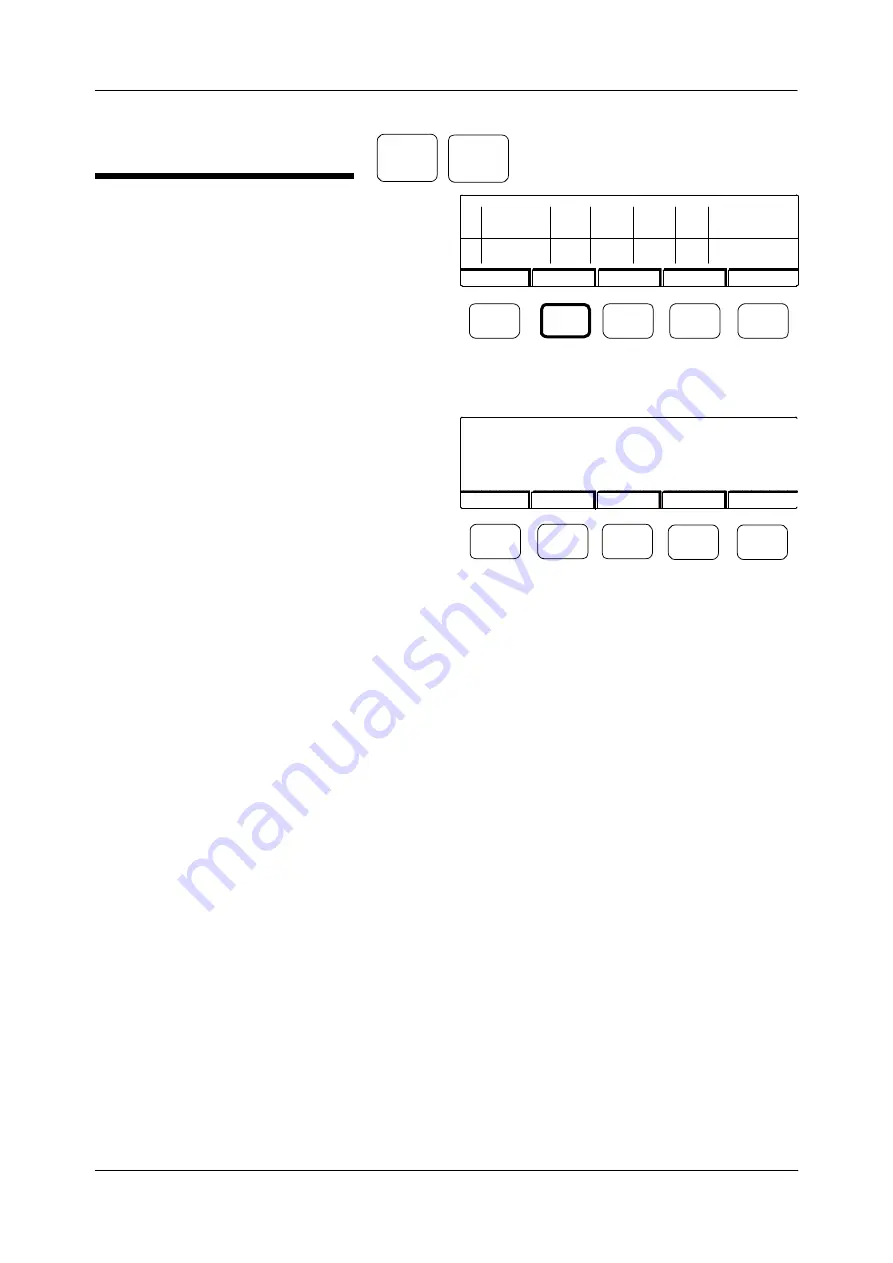
To configure the encoder, follow these steps:

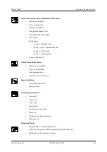
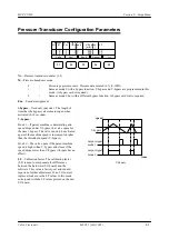
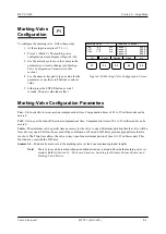
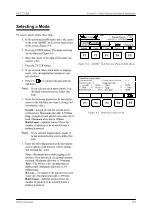
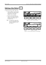
1. At the setup screen (Figure 8-7), press F2

(Enc.1) to configure encoder 1, or press F3

(Enc.2) to configure encoder 2. The encoder-

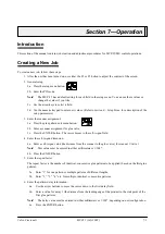
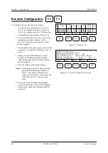
configuration screen displays (Figure 8-8).

2. Use the arrow keys to move the cursor to the

parameter you want to change (refer to

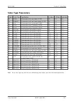
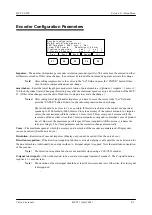
Encoder Configuration Parameters 

on the

following page).

3. Use the numeric keypad to type a value for the

parameter, or use the scroll buttons to select a

value.

4. Either press the ENTER button or wait 3

seconds. The following message displays:

“The change takes effect when the control is

turned on again!”.

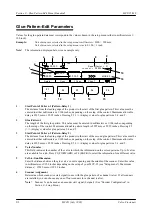
5. Press F3 (OK) to confirm the message.

Notes!

If you place an [X] in a field, you must

press the ENTER button for the new

value to take effect. Before the new

value goes into effect, you can press the

ESC button to recover the previous

value.

6. The control is set by default to minimum

speed (Vmin) for the valves. After changing

encoder data, check the minimum speed for

each valve.

F2

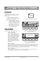
Figure 8-7. Setup Screen

Figure 8-8. Encoder-Configuration Screen

F3

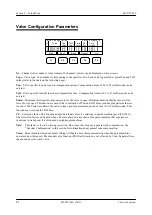
Valve  conf i gur ation

Valve  output s:  4

Nr      Type       Ton    Toff    Tmin    CF     Vmin      M

                       [ms]    [ms]    [ms]    [%]    m/min

  1

  2

F1

F2

F3

F4

F5

07HP/24

07HP/24

9.0

9.0

7.5

7.5

1.0

1.0

100

100

0001

0001

Pres.

Sensor

>>>

Enc 1.

Enc 2.

Encode r  conf igurati on

Modi fy  onl y  at  m ac hine  stop !

00 01 Impul ses =  0001    mm ->

Set

Vmax= 2000  m/m in    ,    R esol uti on=1.00  mm

D i rectio n  r ecogni ti on

:

yes  [      ]

no  [      ]

Z-S ignal on  Sc anner  5 :

yes  [      ]

no  [      ]

F1

F2

F3

F4

F5

Pres.

Sensor

>>>

Enc 1.

Enc 2.

Summary of Contents for MCP-25/MS

Page 1: ...MCP 25 MS Control Manual Number MC051 Release Date June 2004 ...

Page 2: ...ion in this manual is furnished for educational purposes only is subject to change without notice and should not be construed as a commitment by Valco Cincinnati Inc This manual was written and designed at Valco Cincinnati Inc 411 Circle Freeway Drive Cincinnati Ohio 45246 Part Number MC051 Printed in the USA Valco Cincinnati Incorporated 411 Circle Freeway Drive Cincinnati Ohio 45246 TEL 513 874 ...

Page 3: ...ProductName GlueControl ProductModel MCP 25 MS YearofManufacture 2004 conforms to the following standards Safety EN 60204 1 EMCEmissions EN 50081 2 EN 55011 Class A EMCImmunity EN 50082 2 EN 61000 4 2 EN 61000 4 3 EN 61000 4 4 and complies with the requirements of LowVoltageDirective73 23 EEC EMC Directive 89 336 EEC Office of CE Conformance Cincinnati Ohio USA ...

Page 4: ...onents and Options 4 9 Section 5 Installation 5 1 Introduction 5 1 MCP 25 MS Control Installation 5 1 Connecting the Main Power Supply 5 1 Setting the Powerup Selection Switch 5 3 Scanner Installation 5 4 Mechanical Installation of the Scanner 5 4 Electrical Installation of the Scanner 5 4 Encoder Installation 5 6 Mechanical Installation of the Encoder 5 6 Electrical Installation of the Encoder 5 ...

Page 5: ...cription 5 33 Installing the D 12 Sensor 5 33 MW 101 Microwave Sensor 5 34 Description 5 34 Specifications 5 34 Sensor Suitability 5 34 Limitations 5 34 Installing the MW 101 Microwave Sensor 5 36 Digital NPN PNP Sensor 5 37 Description 5 37 Installing the Digital NPN PNP Sensor 5 37 Section 6 Menu Overview 6 1 Introduction 6 1 Initial Screen 6 1 Initial Screen Function Keys 6 1 Learn Function Scr...

Page 6: ... 10 1 Introduction 10 1 Flexoseal Modes 10 1 Accessing the Glue Pattern Edit Main Menu 10 1 Main Screen for Mode 0 Top Down Gluing Tab Only 10 2 Main Screen for Mode 1 Top Down Gluing Tab and 4th Panel 10 2 Main Screen for Mode 2 Top Down Bottom Up Gluing Tab and 4th Panel 10 3 Main Screen for Mode 3 Top Down Bottom Up Gluing Tab Only 10 3 Glue Pattern Edit Parameters 10 4 Selecting 4th Panel or T...

Page 7: ...e Pattern Positions 13 6 Section 14 Job Management Menu 14 1 Introduction 14 1 Function Keys on Page 1 14 1 Function Keys on Page 2 14 1 Function Keys on Screen 3 14 1 Saving a Job 14 2 Loading a Job 14 3 Copying a Job 14 4 Deleting a Job 14 5 Go To Screen 2 14 5 Creating a New Current Job 14 6 Editing a Job in Memory 14 7 Preparing a New Job in Memory 14 8 Renaming a Job 14 9 Go To Screen 3 14 9 ...

Page 8: ...intenance A 1 Weekly Maintenance A 2 3 Month Maintenance A 3 6 Month Maintenance A 4 12 Month Maintenance A 5 Appendix B Wiring Information Older Generation Controls B 1 Back Panel of Field Wirable Control B 1 Description of Back Panel Features B 1 Back Panel of Control with Connector B 4 Description of Back Panel Features B 4 Alarm Beacon Wiring Connections B 5 Appendix C Glue Pressure Software O...

Page 9: ...control is capable of operating a combination of different styles and types of glue valves and dispensing systems Programs or program changes may be made on the fly with the results immediately occurring on the product The system maintains precision through machine speeds up to 2000 m min 6500 ft min With user friendly multi language software valve outputs can be individually compensated and assig...

Page 10: ...ing the control OTHERWISE DEATH OR PERSONAL INJURY COULD OCCUR Only qualified personnel should open and service the control WARNING Promptly repair or replace all worn or damaged electrical wiring and equipment wires OTHERWISE DEATH OR PERSONAL INJURY COULD OCCUR WARNING Properly route all electrical wires OTHERWISE DEATH PER SONAL INJURY OR DAMAGE TO THE MOVING PARTS OF THE MACHINE MAY OCCUR WARN...

Page 11: ...MES Do not wear a face mask when working around the molten adhesive THE MASK MAY TRAP THE FUMES AND DEATH OR PERSONAL INJURY COULD OCCUR WARNING Purge the fluid pressure from the system before disconnecting any part of the system OTHERWISE DEATH OR PERSONAL INJURY COULD OCCUR WARNING Keep the hot melt hoses away from walkways and the moving parts of the hot melt system OTHERWISE PERSONAL INJURY OR...

Page 12: ...ot melt is overheated WARNING Poor ventilation smoking and open flames can cause overheated hot melt to ignite Adequate ventilation must be provided Smoking should be prohibited in the immediate vicinity of the molten adhesive Open flames must be kept away from the area around the molten adhesive OTHERWISE DEATH PERSONAL INJURY OR DAMAGE TO EQUIPMENT COULD OCCUR WARNING Exposed arcing may ignite t...

Page 13: ...innati 2 4 What to Do if Inhalation of Adhesive Fumes Occurs If the adhesive fumes are inhaled immediately follow these steps 1 Take the victim away from the immediate work area 2 Provide the victim with fresh air 3 Call a qualified medical authority ...

Page 14: ...n All wiring should be in conduits or wireways Connecting the Supply of Electrical Power WARNING Electrical connections should be made only by experienced service personnel OTHERWISE DEATH PERSONAL INJURY OR EQUIP MENT DAMAGE COULD OCCUR When connecting the supply of electrical power follow this guideline Connect the control to a clean supply of electrical power Use a dedicated circuit if possible...

Page 15: ...he control is in the valve selection mode pressing a valve selection button causes the programmed glue pattern information to be sent to the valve s selected Pressing the valve selection button a second time will turn off the selected valve s The valve selection buttons have a special function when copying a glue pattern in the glue pattern edit menu A pattern can be copied to a valve by selecting...

Page 16: ... Function 7 Main menu buttons The main menu buttons are used to select the main menus A red LED on the button illuminates when the menu has been selected Note The main menu buttons are active in all menus You can switch to another main menu at any time Job Management Menu Glue Pattern Edit Menu Glue Pressure Edit Menu Inspection Menu Setup Menu Diagnostic Menu 8 LCD display 9 Plus minus scroll but...

Page 17: ...s not illuminate there is a fault with either the 15V or 24V supply 14 Internal supply voltage LEDs 5VDC and 24VDC 15 Help button Pressing this button displays information about the current menu shown in the display 16 Function buttons F1 F5 These buttons correlate to the screen information above them 17 Sensor on off buttons The LED next to the sensor number illuminates when the sensor is on The ...

Page 18: ...V U 0 ENTER U 1 2 2 3 U 3 6 7 8 9 4 1 MCP 25 Learn 5 5 6 6 1 1 2 2 8 8 4 4 3 7 7 3 Figure 4 1 Horizontal Mount Enclosure 10 A Z 1 A Z 10 1 F1 F5 F4 F3 F2 MCP 25 2 1 24V 5V U ESC ENTER 0 U 2 1 5 2 1 2 3 4 5 6 U 6 3 7 8 9 4 1 Learn 5 5 6 6 1 1 2 2 8 8 4 4 3 7 7 3 Figure 4 2 Vertical Mount Enclosure Enclosure Options ...

Page 19: ...ield Wirable Control 11 Power output 115V 60Hz or 230V 50Hz 12 Scanner for marking valve 13 Additional alarm outputs printer and ejector 14 Relay alarm and 24VAC outputs 15 Marking valve 16 Bypass valve connections maximum of 2 17 Scanner 6 or level indicator 18 Pressure transducer connections maximum of 2 19 Fuse F3 24V encoder 0 5 amp GDC 20 Fuse F5 15V encoder 0 5 amp GDC 21 Fuse F4 flow contro...

Page 20: ...ace 4 Fuse F2 24V scanner 0 5AT 5 Fuse F4 24V pressure transducer 1 6AT 6 Fuse F5 15V encoder 0 5AT 7 Fuse F3 24V encoder 0 5AT 8 Scanner connections maximum of 6 9 Alarm 24V 10 Alarm dry contact 11 Glue valve connections maximum of 8 12 Glue inspection maximum of 4 13 Power entry module 14 Marking valve 15 Bypass valve connections maximum of 2 16 Pressure transducers maximum of 2 17 Pump 18 Encod...

Page 21: ... 4 3 Alternate Back Panel for Flexoseal Controls Note MCP 25 MS CM Model Valve connections are standard Key like scanners MCP 25 MS CE Model Valve connections are non Key Note The encoder connector is standard Key M12 not 8 pin DIN Use 155xx310 and scanner cables ...

Page 22: ...dapter boards 5 Valve driver board glue valves 1 4 6 CPU board 7 I O board 8 Special function board bypass Note On old style boards the special function board attaches to the I O board in piggy back fashion On new boards the special function board is integrated into the I O board 1 8 Internal Components 2 3 5 6 7 4 ...

Page 23: ...ector backpanel cable 5m 030xx863 Connector backpanel cable 10m 030xx864 Connector backpanel cable 15m 030xx865 Connector backpanel cable 30m Sensor options 2 or 3 required depending on the level of sensitivity needed For most applications the following laser scanner provides sufficient accuracy 280xx234 NPN Laser Scanner The following laser scanner can be selected for situations that require extr...

Page 24: ...Section 4 Basic Features MCP 25 MS Valco Cincinnati 4 10 1 SE NSOR 2 SCANNER TO MCP 2 SENSOR 1 MO DE Figure 4 4 Skew Detection System Configuration ...

Page 25: ......

Page 26: ...Wire Function International Power Cord Color North American Power Cord Color Line Voltage Brown Black Neutral Blue White Protective Earth Green Yellow Green ...

Page 27: ......

Page 28: ......

Page 29: ...3 4 5 1 2 2 4 5 3 1 ...

Page 30: ......

Page 31: ......

Page 32: ...VCE1000 VALCO VLD500 VLD1000 VLD250 VCE500 VCE250 VLD1000 2 3 10 9 8 5 6 7 4 VALCO 7 9 10 8 5 6 4 3 1 2 VLD250 VLD500 1 HOHNER z B TYP 85 6 10 9 8 7 2 4 5 3 1 ...

Page 33: ...4 8 12 11 10 9 6 7 5 3 2 1 ...

Page 34: ...3 7 9 10 8 5 6 4 1 2 1 4 3 2 ...

Page 35: ...1 3 4 2 ...

Page 36: ...7 9 10 8 3 5 6 4 1 2 ...

Page 37: ...SHD NPN 5 4 3 24V Low Level Detector 0V 1 2 ...

Page 38: ......

Page 39: ......

Page 40: ......

Page 41: ......

Page 42: ......

Page 43: ...3 4 5 6 2 3 1 5 6 4 1 2 ...

Page 44: ......

Page 45: ......

Page 46: ......

Page 47: ......

Page 48: ......

Page 49: ...RODUCT 7 10 9 8 3 5 6 4 1 2 8 10 9 2 5 7 6 3 4 1 ...

Page 50: ......

Page 51: ......

Page 52: ...6 8 10 9 7 1 3 5 4 2 ...

Page 53: ......

Page 54: ......

Page 55: ...6 8 10 9 7 1 3 5 4 2 ...

Page 56: ...VA LC O CI NCIN NA TI INC 513 87 4 6550 5 13 87 4 6550 VALC O C INCIN NATI INC ...

Page 57: ......

Page 58: ......

Page 59: ......

Page 60: ......

Page 61: ......

Page 62: ......

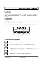
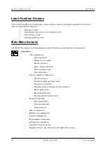
Page 63: ...ned off Note The initial screen appears only when power is turned on After you access the other menus you cannot return to the initial screen without turning the unit off and then back on Figure 6 1 Initial Screen Initial Screen Function Keys Section 6 Menu Overview LCD Contrast Adjustment Pressing the F1 function key lightens the display screen LCD Contrast Adjustment Pressing the F2 function key...

Page 64: ...nu Valve configuration Valve time on off Minimum valve on time Encoder allocation Speed compensation factor Threshold speed Vmin Glue pattern mode Pressure transducer configuration Encoder allocation Pressure transducer operating mode Glue pressure regulation Maximum pressure settings for a given transducer Bypass opening time Bypass threshold speed Entering values for pressure curve Encoder confi...

Page 65: ... Stitch mode Mode 3 Jogging mode Scanner lockout jam Glue Pressure Edit Menu Delete a pressure table Copy a pressure table Glue pressure curve Pressure curve learn mode Inspection Menu Glue inspection menu Jam preventer Job Management Menu Save a job Load a job Copy a job Delete a job Create a new current job Edit a job Prepare a new job in memory Rename a job Diagnostic Menu Display of the curren...

Page 66: ...3b Enter a scanner assignment for glue valve 3c Press the ENTER button The cursor moves to the cell to gun field 4 Enter the cell to gun dimension 4a Enter a cell to gun value the distance from the scanner to the glue valve for scanner 1 valve 1 Note This value must be entered in either millimeters or 1 100 4b Press the ENTER button 5 Enter the repeat factor The repeat factor is the number of iden...

Page 67: ...essure in the second field to the right of P This value is normally 100 9f Enter other speed and pressure values between the minimum and maximum settings if desired 9g Program other pressure tables 2 if desired You can use the copy button to copy a pressure table to another location 10 Complete pressure table 1 10a Return to pressure table 1 after entering values for other pressure tables 10b Oper...

Page 68: ...enu increase the Ton value 0 1 25 milliseconds in the valve setup menu If the start of the glue pattern begins sooner than the value seen in the glue pattern edit menu decrease the Ton value 0 1 25 milliseconds in the valve setup menu Pattern length If the pattern is longer than the value seen in the glue pattern edit menu increase the Toff value 0 1 25 milliseconds in the valve setup menu If the ...

Page 69: ...lve type 4 Either press the ENTER button or wait three seconds The valve type displays Note Each valve type includes default parameter values LCD OK Valve c put s 4 Nr Typ min M LCD F1 F2 F3 F4 F5 Ent er PI N Code _ _ _ _ _ _ _ _ or set contr ast Section 8 Setup Menu Figure 8 2 Initial Message in Setup Menu Figure 8 3 Setup Menu Figure 8 1 Setup Menu Icon Button Figure 8 4 Type Column Pres Enc 2 S...

Page 70: ...open Minimum duration that the valve will be forced to stay open This function is used if the combination of Ton and Toff times produce glue patterns that are too short The Tmin time allows the valve to stay open for a minimum period of time 0 1 25 milliseconds This function may override the Toff time CF Correction factor This function adapts individual valves to variations in parent machine speed...

Page 71: ...09 369 24 Pneumatic glue valve w 24VDC MAC 15 0 12 0 1 5 10 05P 24 Pneumatic glue valve w 24VDC MAC 20 0 18 0 2 0 11 07HP 24 Pneumatic glue valve w 24VDC MAC 7 5 7 0 1 5 12 08HP 24 Pneumatic glue valve w 24VDC MAC 8 5 8 5 1 5 13 SP 1 24 Pneumatic glue valve w 24VDC MAC 10 0 10 0 1 5 14 SP1MM24 Pneumatic mini module valve w 24VDC MAC 10 0 9 5 1 5 15 EL XC Electromatic X hot melt valve 24VDC 4 6 5 0...

Page 72: ... on the following page 3 Use the numeric keypad to enter a value for the parameter or use the scroll buttons to select a value 4 Either press the ENTER button or wait 3 seconds The new value takes effect Figure 8 5 Setup Menu Figure 8 6 Pressure Transducer Configuration Screen Transducer confi gurati on 1 2 0 0 1 0 1 0 0001 0001 30 30 Enc Nr M t Bypass s V Bypass m min LF F1 F2 F3 F4 F5 Valve Enc ...

Page 73: ...ypass the valve opens for the time t bypass The valve can only be activated again if the machine speed is increased to higher than the threshhold speed V bypass Mode 2 The valve opens if the parent machine speed is higher than V bypass and closes if the speed drops lower than V bypass t bypass has no effect LF Calibration factor The calibration factor LF is used to compensate for differences betwe...

Page 74: ...urned on again 5 Press F3 OK to confirm the message Notes If you place an X in a field you must press the ENTER button for the new value to take effect Before the new value goes into effect you can press the ESC button to recover the previous value 6 The control is set by default to minimum speed Vmin for the valves After changing encoder data check the minimum speed for each valve F2 Figure 8 7 S...

Page 75: ...n is 1 mm or less This accuracy can be increased if the resolution of the encoder is less than 1 mm one impulse corresponds to less than 1 mm of product travel However the maximum possible speed Vmax required with this accuracy reduces the ratio accordingly The Vmax parameter and the resolution change automatically Vmax The maximum speed at which the accuracy and resolution of the encoder are main...

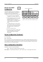
Page 76: ...Flts Max field and enter the number of consecutive faults that are acceptable before activating a machine stop Figure 8 9 Sensor and Alarm Configuration Screen Sensor and alarm confi gur ati on 1 2 1 1 1 X 1 CF No Enc Cons Flts Max 010 Other outputs Relays 24V 24V F1 F2 F3 F4 F5 Valve Pres Enc 1 Enc 2 100 100 2 3 X 4 X 2 3 4 Sensor Configuration Parameters No Sensor number Enc Encoder number CF Co...

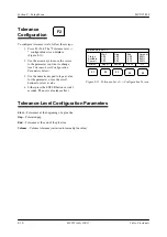
Page 77: ... compensation time Compensation times of 0 1 to 25 milliseconds can be entered Tmin The minimum valve specific time necessary for the valve to open Minimum duration that the valve will be forced to stay open This function is used if the combination of Ton and Toff times produce glue patterns that are too short The Tmin time allows the valve to stay open for a minimum period of time 0 1 25 millisec...

Page 78: ...o type a value for the parameter or use the scroll buttons to select a value 4 Either press the ENTER button or wait 3 seconds The new value takes effect F2 Tolerance Level Configuration Parameters Start Tolerances at the beginning of a glue line Gap Tolerated gap End Tolerance at the end of the glue line Volume Volume tolerance variation to learned glue value Figure 8 11 Tolerance Level Configura...

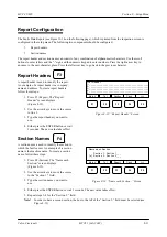
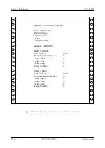
Page 79: ...______ 2 ____________________________________________ 3 ____________________________________________ 4 ____________________________________________ 5 ____________________________________________ F1 F2 F3 F4 F5 Figure 8 13 Name each Section Screen Mark V Tol Report Clock Name each Section Section 1 Section 1___ x Section 2 Section 2___ F1 F2 F3 F4 F5 Report Configuration The Faults Data Report see ...

Page 80: ...01 01 2002 03 09 AM XYZ Company Inc 400 Main Street Cincinnati Ohio 45246 513 874 6550 Job name JOBNAME Saturn 3 per Job Total Products 18000 Products outside Tolerance 15 Faults Start 4 Faults End 11 Faults Gap 0 Faults Volume 0 Saturn 3 Shift Total Products 50000 Products outside Tolerance 36 Faults Start 13 Faults End 23 Faults Gap 0 Faults Volume 0 ...

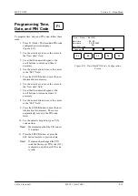
Page 81: ...rsor to the New date field 7 Use either the numeric keypad or the scroll buttons to enter a new date if necessary 8 Use the arrow buttons to move the cursor to the SET field 9 Press the ENTER button to enter the new information into memory The cursor automatically moves to the PIN code field 10 Use the numeric keypad to type a PIN code number Note Maximum length of the PIN code is 11 numbers 11 Pr...

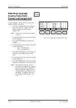
Page 82: ...arrow keys to move the cursor to the desired language 3 Press the ENTER button to select the new language 4 Use the arrow keys to move the cursor to the desired date format Euro day month year USA month day year 5 Press the ENTER button to select the desired date format X displays in the selected field 6 Use the arrow keys to move the cursor to the desired length unit 7 Press the ENTER button to s...

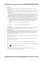
Page 83: ...hine operates below the minimum speed setting Section 9 Glue Pattern Edit Menu Standard Mode 2 Stitch Mode Stitch mode is used for discontinuous lines This mode is useful for economical application of long lines of glue It allows different input possibility of bead length and gap length Intermittent gluing is also possible The control will take into account that each pattern ends with applied glue...

Page 84: ...rn 2 Pattern Delay 2 The distance from the leading edge of the product to the start of the second glue pattern This value must be entered in either millimeters or 1 100 inches depending on the setup of the control Maximum allowable delay is 9999 mm or 99 99 inches Pressing F5 displays values for glue patterns 3 4 and 5 4 Valve Number This field indicates the number of the valve to which the inform...

Page 85: ...r the last glue line Example 2 glue lines delay 3 start of repeat glue length 3 must be 0 4 glue lines delay 5 start of repeat glue length 5 must be 0 9 Unit of Measure This field indicates the unit of measure millimeters or inches that has been selected in the setup menu See Section 11 Setup Menu for information about how to change the unit of measure 10 Scanner Lockout This field contains the lo...

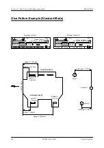
Page 86: ...Leading edge delay 1 62mm pattern 1 62 mm pattern 1 40 mm delay 2 292mm channel valve 1 pattern 2 32 mm channel valve 2 Channel valve 1 Glue Pattern Example Standard Mode 1 1 00119 00054 00140 00062 000 00 Job 1 mm Lockout 000000 Repeat factor 03 Channel valve 2 2 1 00065 00062 00292 00040 00032 Job 1 mm Lockout 0 00000 Repeat factor 01 Delete Copy Chan Chan Delete Copy Chan Chan ...

Page 87: ......

Page 88: ...esired field Continuous gluing mode 1 In continuous gluing mode see Figure 9 7 the operation of the valve depends on the Vmin minimum speed setting The valve turns on when the parent machine operates above the minimum speed setting and turns off when the parent machine operates below the minimum speed setting Therefore the parameters cannot be changed in the glue pattern edit menu You can press F5...

Page 89: ...glue pattern or F4 Cancel to cancel the operation and retain the current glue pattern data Note If you press F4 Cancel all previously entered data will be deleted including the cell to gun distance F1 Figure 9 8 Glue Pattern Edit Menu Figure 9 9 Glue Pattern Edit Menu with Message Repeat factor 01 F1 F2 F3 F4 F5 1 1 00000 00000 00000 0000 0 00000 Job 1 mm Loc kout 0 00000 Yes Cancel F1 F2 F3 F4 F5...

Page 90: ...n copy func tion message displays Figure 9 13 and the LED on the valve selection button stops flashing and becomes solid green Note If you press the wrong valve selection button and have not yet copied data press the button again to deselect it 4 Press F2 Yes to begin copying data or F4 Cancel to cancel Note If you press F2 Yes the old glue pattern parameters are overwritten F2 Copy g lue patter n...

Page 91: ...change values for Automatic Gluing follow these steps 1 Use the arrow keys to move the cursor to the Start Delay field Use the numeric keypad or the scroll buttons 10 1 1 10 to enter a value for the delay 2 Press the ENTER button 3 Use the arrow keys to move the cursor to the End Gap field Use the numeric keypad or the scroll buttons 10 1 1 10 to enter a value for the end gap 4 Press the ENTER but...

Page 92: ... 1 and 2 Mode 2 top down bottom up gluing tab only two channels valves 1 and 2 sensor 1 Mode 3 top down bottom up gluing tab and 4th panel four channels valves 1 and 2 sensor 1 valves 3 and 4 sensor 3 Accessing the Glue Pattern Edit Main Menu The glue pattern edit screens allow you to edit glue patterns To access the glue pattern edit main menu follow this step 1 Press the glue pattern edit icon b...

Page 93: ...ncinnati 10 2 MC051 July 2002 F1 F2 F3 F4 F5 Main Screen for Mode 0 Top Down Gluing Tab Only Figure B 2 Glue Pattern Edit Main Menu for Mode 0 Main Screen for Mode 1 Top Down Gluing Tab and 4th Panel F1 F2 F3 F4 F5 Figure B 3 Glue Pattern Edit Main Menu for Mode 1 ...

Page 94: ... 3 MC051 July 2002 Main Screen for Mode 2 Top Down Bottom Up Gluing Tab and 4th Panel Main Screen for Mode 3 Top Down Bottom Up Gluing Tab Only Figure 10 4 Glue Pattern Edit Main Menu for Mode 2 Figure 10 5 Glue Pattern Edit Main Menu for Mode 3 F1 F2 F3 F4 F5 F1 F2 F3 F4 F5 ...

Page 95: ...u will go to the function pictured on the button 1 F1 Toggles between 4th panel gluing and tab gluing This button toggles between 4th panel gluing and tab gluing for the selected valve 2 F2 Toggles between single pattern and pattern skip pattern This button toggles between single pattern and pattern skip pattern gluing for the selected valve 3 F3 Allows you to select either extended tab or normal ...

Page 96: ...g To select 4th panel or tab gluing follow these steps 1 To select 4th panel gluing press F1 The 4th panel gluing screen Figure 10 6 displays 2 To return to the tab gluing screen press F1 The tab gluing screen Figure 10 7 displays Figure 10 7 Tab Gluing Screen F1 F2 F3 F4 F5 Figure 10 6 4th Panel Gluing Screen F1 F2 F3 F4 F5 ...

Page 97: ...Pattern Screen Tab Side Selecting a Glue Pattern Mode To select a glue pattern mode follow these steps 1 To select a single glue pattern press F2 A single glue pattern is selected and displayed Figure 10 8 2 To select a pattern skip pattern glue pattern press F2 A pattern skip pattern glue pattern is selected and displayed Figure 10 9 F1 F2 F3 F4 F5 F1 F2 F3 F4 F5 ...

Page 98: ...l tab gluing follow these steps 1 Press F3 The tab selection screen displays Figure 10 10 2 To select a mode move the cursor to the appropriate selection field and press the ENTER button 3 Press F5 to return to the glue pattern edit main menu Figure 10 10 Tab Selection Screen F1 F2 F3 F4 F5 selection field for extended tab gluing selection field for normal tab gluing ...

Page 99: ...F1 F2 F3 F4 F5 ...
Page 100: ...luing function field is available only if the tab scanner position has been selected 4a Use the arrow keys to move the cursor to the automatic gluing function field 4b Press the ENTER button The automatic gluing function screen Figure 10 12 displays 5 At the start length field enter the start length dimension 6 Use the right arrow button to move the cursor to the end length field 7 Enter the end l...

Page 101: ...a channel follow these steps 1 To select channel 2 press F5 F1 position in mode 2 The channel 2 screen Figure 10 13 displays 2 To return to the channel 1 screen press F5 F1 position in mode 2 The channel 1 screen Figure 10 14 displays Figure 10 13 Channel 2 Screen Figure 10 14 Channel 1 Screen F1 F2 F3 F4 F5 F1 F2 F3 F4 F5 ...
Page 102: ...ve P represents the glue pressure as a percentage of the maximum glue pressure allowed To access the glue pressure edit menu follow this step 1 Press the glue pressure edit menu icon button Figure 10 15 The glue pressure edit menu displays Figure 10 16 The glue pressure edit menu contains the glue pressure table Figure 10 15 Glue Pressure Edit Menu Icon Button Figure 10 16 Glue Pressure Edit Main ...

Page 103: ...ssure table 3 F3 Raises values in pressure table only air pressure values are incremented not speed values 4 F4 Lowers values in pressure table only air pressure values are incremented not speed values 5 F5 Imports parent machine and glue pressure values Pressing F5 Insert automatically imports the parent machine speed and corresponding glue pressure values into the glue pressure table See Section...

Page 104: ...e edit menu contains the glue pressure table Section 11 Glue Pressure Edit Menu Figure 11 1 Glue Pressure Edit Menu Icon Button Glue Pressure Edit Parameters F1 F2 F3 F4 F5 3 5 6 Delete Insert 1 1 2 4 7 8 9 10 11 1 Pressure Transducer Number This field contains the number of the selected pressure transducer for the displayed glue pattern data 2 Output Pressure Percent This field displays current o...

Page 105: ... transducer has been selected in the setup menu Note This option is not visible if it is not selected in special setup Note This option is not visible if it is not selected in special setup 7 F1 Press F1 to display the glue pressure curve for pressure transducer 2 Up to two pressure transducers are available in one job 8 F2 Pressing F2 Delete deletes the current pressure table 9 F3 Pressing F3 inc...

Page 106: ...e glue pressure curve Note The glue pressure data can either be entered manually or with the Learn function see the following pages for procedures Examples of Glue Pressure Values Attention Note the maximum allowable operation pressure of the pressure container Corresponding Glue Pressure psi bar Input in Pressure Transducer Air Pressure Output psi bar 1 1 2 1 3 1 5 1 7 1 10 1 100 72 6 72 6 160 12...

Page 107: ...e pressure required at the minimum speed of the parent machine 1g Enter a pressure and check the amount of glue that is applied 1h Use the numeric keypad to adjust the pressure if necessary 2 Enter the necessary glue pressure at maximum speed of the parent machine 2a Operate the parent machine at the maximum production speed for product gluing 2b Move the cursor to the field below max 2c Enter the...

Page 108: ...n speed make sure that the glue volume being applied is correct 2 Press F5 Insert to import the current parent machine speed and corresponding glue pressure values into the glue pressure edit table Note The screen cursor is automatically placed in the field that was imported Note The control will sort the other values for speed and pressure numerically 3 Use either the numeric keypad or the plus m...

Page 109: ...eps 1 Use the arrow keys to move the cursor to the field that you want to change see Glue Pressure Edit Parameters in this section 2 Use either the numeric keypad or the scroll buttons 10 1 1 10 to enter new values for the field 3 Press the ENTER button to enter the new information into memory Press the ESC button if you have entered incorrect data To change all of the the glue pressure values bet...

Page 110: ... valve Figures 12 2 and 12 3 Up to four valves can be displayed Config Jam Pattern 3 Section 12 Inspection Menu Figure 12 1 Inspection Menu Icon Button 1 Valve number This number indicates the valve on which the display is based 2 Bar graph The bar graph shows the actual glue volume compared to 100 3 100 base line This line indicates the learned value 4 F1 Press F1 Config to display the inspection...

Page 111: ...raph shows the actual position of the glue pattern 5 End tolerance This value represents the maximum allowable deviation from the programmed end of the glue pattern position after a fault occurs 1 3 5 4 7 8 9 10 11 Figure 12 3 Glue Volume Bar Graph for System with Three Valves 6 Baseline This line indicates the programmed glue position 7 Length field This field indicates the length of the glue lin...

Page 112: ... This field contains the distance between the scanner and the sensor 6 Marking valve ejector on off This field indicates whether the marking valve ejector is turned on or off 7 F1 Press F1 Mark to display the marking valve data screen 8 F2 Press F2 Counter to diplay the fault counter data screen 9 F3 Press F3 Tol to display the tolerance data screen 10 F4 Press F4 Fault to display detailed informa...

Page 113: ...Use the numeric keypad to type the number of the scanner 1 7 that you want to assign Then press the ENTER button Press the plus minus scroll buttons to select and enter the number of the scanner you want to assign To change the assigned scanner to sensor distance follow these steps 1 Use the arrow keys to move the cursor to the scanner distance field 2 Change the assigned scanner distance by using...

Page 114: ...e ENTER button Auto is activated 4 To change the length parameter 4a Use the arrow keys to move to the length field 4b Use the plus minus scroll buttons to enter the new parameter 5 To select auto length 5a Use the arrow keys to move cursor to the auto field across from the length field 5b Press the ENTER button Auto is activated 6 Press F5 Purge 1 if you want to purge the marking valve 7 Press F1...

Page 115: ...unter to zero enter PIN code Figure 12 13 2 Enter the PIN code 3 Take one of the following actions Press F3 OK if the pin code you entered is correct Press F4 Cancel to return to the counter inspection screen Press F2 PIN to change the PIN code The Change PIN screen displays Figure 12 14 Enter the old and new PIN codes Then press F1 OK Figure 12 12 Details Screen Fault Evaluation Section 1 _ _ _ p...

Page 116: ...ion screen or the setup menu Figure 12 15 Tolerance Data Screen 1 2 3 4 1 large 1 large 1 large 1 large Start 0 20 End 0 20 Total 0 50 Amount 050 OK F1 F2 F3 F4 F5 F3 Fault Data To inspect fault data follow these steps 1 At the inspection screen press F4 Fault to display the fault data screen Figure 12 16 2 Press F3 Prev to see up to 5 of the last faults for a particular inspection channel 3 If no...

Page 117: ...y contact will either be closed when selection switch is in N O position or opened when selection switch is in the N C position To reset the relay automatically the control waits for the machine to stop Then after additional time expires the contact or any other alarm output defined by parameter 7441 will be released and the Jam message disappears from the screen The release time is adjustable bet...

Page 118: ...n 12 Inspection Menu MCP 25 MS Valco Cincinnati 12 9 Jam Function Overview Machine Speed t Relay Output Parameter 7441 11 t Scanner t Add Output Parameter 7442 xx t JAM Release Time Re Arm Speed Threshold JAM ...

Page 119: ... ejector marking valve Learn reference values Learn glue pattern position Accessing the Learn Function To access the learn function follow this step 1 Press the Learn button The Learn data screen displays Figure 13 1 Figure 13 1 Learn data screen Volume Dist Refer Pattern Learn data F1 Glue volume F2 Distance Sensor ejector F3 Reference value F4 Learn glue pattern End F1 F2 F3 F4 F5 ...
Page 120: ...leted one of the three following screens displays Figures 13 2 13 3 and 13 4 F1 F2 F3 F4 F5 Again The learn procedure for channel 1 2 was not successful Please try again Cancel F1 F2 F3 F4 F5 OK The learn procedure finished successfully F1 F2 F3 F4 F5 OK The learn procedure was canceled Figure 13 2 Figure 13 3 Figure 13 4 ...

Page 121: ...easuring cycle starts and the measuring glue volume values please wait message displays Figure 13 8 Note Pressing F4 Cancel cancels the learn function 4 When the learn cycle is complete one of the learn results screens displays Figures 13 2 13 3 or 13 4 If the result was unsuccess ful repeat this procedure Note If the pressure of the system is reduced the glue volume will be reduced also which can...

Page 122: ...gh the system The distance between the sensor and the marking valve ejector is updated Note If the distance between the sensor and the marking valve ejector is not set correctly good boxes can be ejected and faulty boxes will not be ejected Note The distance between the sensor and the marking valve ejector can also be set in the setup menu see Section 8 Setup Menu Figure 13 9 The Learn data screen...

Page 123: ... 2 inches before and after the glue line Pressing F2 Contin sets the sensor to continous mode and ends this learn function procedure 2 Press F1 Onetime to select one time mode The screen in Figure 13 15 displays 3 Start the machine without glue and run one box through the system 4 Press F2 Yes The measuring cycle starts and the Measuring reference values please wait message displays Figure 13 16 V...

Page 124: ...F1 F2 F3 F4 F5 Yes Learn glue pattern for channel 1 2 Start machine and gluing and press F2 to start Cancel Figure 13 18 F1 F2 F3 F4 F5 Measuring glue pattern values please wait Cancel Figure 13 19 Learning Glue Pattern Positions If all the data ratio comp and or valve comp in the setup screen is correct it should not be necessary to teach the glue pattern position However if these settings are in...

Page 125: ...s you to save and maintain the parameters of glue patterns and glue pressure curves You can save up to 100 different jobs in memory To access the job management menu follow this step 1 Press the job management icon button Figure 14 1 The first page of the job management menu displays Note The job management menu contains three screens Screen 1 Figure 14 2 Screen 2 Figure 14 3 and Screen 3 Figure 1...

Page 126: ...es to answer yes to the Save job message To save a current job that was loaded from memory and then modified 1 Press F1 Save The Data have been changed message displays Figure 14 5 2 Either press F2 Yes to replace the previous job all data that was saved under the old job will be overwritten or press F3 Name to save the current job under a new name old job remains in memory Note An asterisk next t...

Page 127: ...er letters and the sign and the numeric keypad to enter numbers Pressing the right arrow key advances you to the next character place pressing the left arrow key takes you back to the previous character 5 Press F2 Yes to answer yes to the Save job message The ATTENTION Overwrite current job data message displays 6 Press F2 Yes The current job data will be overwritten by the new information F2 Figu...

Page 128: ...arac ters You use the scroll buttons to enter letters and the sign and the numeric keypad to enter numbers Pressing the right arrow key advances you to the next character place pressing the left arrow key takes you back to the previous character 4 Press F2 Yes to copy the job Avai lable 98 Jobs 16 02 2001 01 57 Cur r ent Job 1 16 01 01 Testjob1 05 10 01 Testjob2 15 12 01 Save Load Copy Delete F1 F...

Page 129: ... Screen 2 To go to the second page of the job management menu follow this step 1 Press F5 Screen 2 of the job management menu displays F4 F5 Figure 14 11 Job Management Menu Figure 14 12 Job Management Menu with Message Avai lable 98 Jobs 16 02 2001 01 57 Curr ent Job 1 16 01 01 Testjob1 05 10 01 Testjob2 15 12 01 Save Load Copy Delete F1 F2 F3 F4 F5 Avai lable 98 Jobs 16 02 2001 01 57 Curr ent Jo...

Page 130: ... takes you back to the previous character 4 Press F2 Yes The glue pattern edit menu displays Figure 14 15 The new job contains default values that can be used or changed to create your new job Cell to gun values scanner assign ments and the pressure tables are copied from the last active job current job Delay and glue pattern lengths are set to 0 5 Enter new values as necessary Note You can operat...

Page 131: ...or the numeric keypad enter the new value Note Press F2 Press menu page 1 to change the glue pressure values F2 Delete menu page 2 to delete glue pattern data and F3 Copy menu page 2 to copy glue pattern data to another channel See Section 9 Glue Pattern Edit Menu and Section 11 Glue Pressure Edit Menu for param eter descriptions 5 Press F1 End when you have finished editing a job in memory The jo...

Page 132: ...values for the glue pattern see Section 9 Glue Pattern Edit Menu 5 Press F2 Press The glue pressure edit menu displays Figure 14 20 Note When the Prepare function is used the glue pressure edit menu provides the following default values Metric V meters per minute V 0020 0100 0000 0000 P 010 035 000 000 Imperial V feet per minute V 0080 0400 0000 0000 P 010 035 000 000 6 Enter the values for the gl...

Page 133: ...next character place pressing the left arrow key takes you back to the previous character 4 Press F2 Yes to enter the new job name The old name is replaced with the new name Note F2 Yes appears only if the name has been changed Go to Screen 3 To go to screen 3 of the job management menu follow this step 1 Press F5 Screen 3 of the job management menu displays Renaming a Job F4 F5 Figure 14 21 Job M...

Page 134: ... are made to setup parameters Back up to Flash memory F1 To initiate a backup via the job management menu complete the following steps 1 Press F5 until the function Backup appears above function key F1 in screen 3 of the job management menu see Figure 14 23 2 Press F1 to start the Backup function If a backup is already stored in Flash memory a message will display see Figure 14 24 3 Make sure that...

Page 135: ...ata with the backup 4 When the second warning message displays Figure 14 27 press F4 to confirm that you want to overwrite ALL job and setup data 5 Switch the unit off and then switch it back on F2 Figure 14 25 Job Management Menu screen 3 Figure 14 26 Figure 14 27 ATTENTION Stop the machine before using the Restore Function All valves will be switched off during the procedure All current settings...

Page 136: ...available in the Special Diagnostic Function Refer to the Service Manual for MCP 25 MS and FS Controls MC052 for information about accessing this function When you access the Special Diagnos tic Function the screen to the right displays see Figure 14 29 To erase the data from Flash memory complete the following steps 1 Press F1 to start the Erase function Two warning messages display to confirm yo...

Page 137: ... character set compatible with a serial connection to the rear panel printer connection COM 3 see Section 5 Installation F1 Section 15 Diagnostic Menu Figure 15 1 Diagnostic Menu Icon Button Note Either a laptop or a desktop PC with terminal emulation software can be used to enter setup param eters into a file serial interface Options TTY emulation 9600 8 1 N 9600bps 8 Data bits 1 Stop bit no pari...

Page 138: ...d for the current job E Error The valve driver is defective or has been removed The valve driver has not been installed 3 Pressure transducers 1 and 2 Percent of output pressure 4 Encoders 1 and 2 Machine speed feet or meters per minute 5 Bypass valves 1 and 2 L Not active H Active E Error The bypass valve has not been configured see Section 8 Setup Menu Pressure Transducer Configuration 6 Com 1 a...

Page 139: ...ion The version numbers of the main and sensor CPUs display Viewing Sensor Diagnostics To view sensor diagnostics follow this step 1 From the Diagnostic Menu screen press the F5 button The diagnostic details screen displays Figure 15 3 F2 Figure 15 3 Diagnostic Details Screen F5 F1 F2 F3 F4 F5 Nr Type Cur Measured Length Glue Learned Glue Box 1 AS 601 0 CGS 30 30 10 00 5 00 50 70 48 65 12 NA ...

Page 140: ...ace fuse if necessary Make sure the scanner assignment to the valves is correct glue pattern edit menu Make sure the correct CPU boards and valve driver boards are in place diagnostics 2 The scanner is operating but the valve s is are not operating Valve driver is not available for the selected valve s Valve cable is not connected properly Scanner assignment to the valves is incorrect glue pattern...

Page 141: ...structed Mount scanner correctly 4 The valves are operating but the glue volume is not correct Check the pressure table s Size of valve nozzle incorrect Pressure transducer not operating properly Check the operation of the fluid regulators Bypass valve duration time is too long Pump is not operating correctly Obstructions in glue supply hoses Thickened glue in glue supply hoses Make sure there is ...

Page 142: ...lve s Increase the scanner lockout value glue pattern edit menu Enter proper ratio compensation setup menu 6 Length and position of the glue pattern are not correct Ratio compensation is incorrect Correction factor is incorrect Incorrect glue mode is selected Incorrect repeat factor is entered Incorrect unit of measure is being used Scanner assignments are incorrect Incorrect encoder is assigned t...

Page 143: ... of the valves are operating Valve not enabled Check the scanner assignment s glue pattern edit menu Check the encoder assignment s setup menu Check the valve cable connections Incorrect glue mode for valve in question Make sure the valve selection button on the front panel has been pressed A LED on the button will illuminate when a valve has been selected Check the scanner assignment s glue patte...

Page 144: ...setup menu Bypass valve not operating properly Obstructions in the bypass valve s hoses Fluid regulators not adjusted properly Increase the bypass valve s threshhold Vbypass Increase the bypass valve s activating duration Tbypass Make sure the bypass valve is operating correctly Make sure the bypass valve s hoses are free from obstructions Make sure fluid regulators are adjusted properly 13 The en...

Page 145: ...tput Up to 4 valves Coil voltage Up to 65W per channel maximum 160 for the entire unit Job storage capacity 100 jobs Scanner inputs 6 PNP or NPN scanners 24VDC plus a fifth encoder start signal input zero signal Pressure transducer 2 transducers 0 10V or 0 20mA Computer hardware interface RS232 and fiber optic other optional interfaces are available Bypass valve output Maximum 2 valves 24VDC Encod...

Page 146: ...eeway Drive Cincinnati Ohio 45246 TEL 513 874 6550 FAX 513 874 3612 MCP 25 MS Spare Parts List Description Part Number PCB assembly CPU 151xx515 PCB assembly I O board 151xx483 PCB assembly power supply 151xx456 PCB assembly valve driver 151xx484 Module assembly display keyboard 080xx859 PCB assembly sensor CPU 151xx487 Sensor adapter board digital Lut 3 151xx459 Sensor adapter board MW 101 151xx5...

Page 147: ...n 12 mm bore 155xx085 Encoder Type 85 1400 pulses per revolution 12 mm bore 155xx086 Encoder Type 85 2000 pulses per revolution 12 mm bore 155xx087 MCP 25 Installation Kit 091XX441 Description Qty Part Number Fuse 500MA 2 085xx219 Fuse 2 0 AMP 2 085xx220 Fuse 6 3 AMP 2 085xx221 Fuse 4A SLO BLO 2 085xx181 Connector tool wire insertion 2 070xx267 Connector PC card 2 070xx011 Cable power IEC320 US pl...

Page 148: ...nd 85 15 m 49 ft for field wireable back panel option 030xx496 Encoder cable Types 30 and 85 25 m 82 ft for field wireable back panel option 030xx497 Encoder cable Types 30 and 85 5 m 16 ft for connector back panel option 030xx797 Encoder cable Types 30 and 85 10 m 33 ft for connector back panel option 030xx798 Encoder cable Types 30 and 85 15 m 49 ft for connector back panel option 030xx799 Encod...

Page 149: ...771 CGS 30 gate sensor cable 5m 16 ft 030xx762 CGS 30 gate sensor cable 10m 33 ft 030xx763 CGS 30 gate sensor cable 15m 50 ft 030xx764 D 12 sensor cable 5m 16 ft 030xx604 D 12 sensor cable 10m 33 ft 030xx596 MW 101 microwave sensor cable 5m 16 ft 030xx765 MW 101 microwave sensor cable 10m 33 ft 030xx766 MW 101 microwave sensor cable 15m 50 ft 030xx767 Digital NPN PNP sensor 5m 16 ft 030xx765 Digit...

Page 150: ...J connector cable 5 m 16 ft for use with field wirable back panel 030xx605 EPC J connector cable 10 m 33 ft for use with field wirable back panel 030xx614 EPC J connector cable 5 m 16 ft for use with connector back panel 030xx801 EPC J connector cable 10 m 33 ft for use with connector back panel 030xx802 EPC J connector cable 2 m 6 ft for use with 5 pin M12 connector 030xx850 EPC J connector cable...

Page 151: ...itioned equipment unless specified otherwise at the time of purchase will be warranted as described above for a period of ninety 90 days from the date of shipment by Valco Cincinnati Components purchased by Valco Cincinnati Inc from others for inclusion in its products are warranted only to the extent of the original manufacturer s warranty In no event shall Valco Cincinnati Inc be liable for indi...

Page 152: ...ed at that time Any part that fails during the warranty period shall be returned prepaid to Valco Cincinnati by the customer for disposition Note Upon request Valco Cincinnati personnel are available to repair or replace such parts at the customer s facility Charges for this service include travel time and expenses If an equipment problem is the result of customer abuse improper installation or op...

Page 153: ...tems only OTHERWISE DAMAGE TO EQUIPMENT COULD OCCUR Action Date Shift Initials 1 Clean the exterior portion of the glue valves nozzle tips glue heads etc 2 Purge the glue valves if necessary and ensure proper glue flow 3 Ensure that air and glue pressure settings are correct 4 If using glue inspection Ensure that sensor is clean Lens must be clean and clear with no scratches Check sensor for prope...

Page 154: ...assemble the fluid section 6 Using the 3 way purge valve on the output of the glue filter purge all air from the system 7 Purge each valve in the system Approximately 1 2 ounces of glue should be purged for proper glue flow 8 Check for any glue leakage on the needle seat Replace the needle plunger assembly and seat if leaks or dripping occurs 9 For non contact valves only Apply a small amount of l...

Page 155: ...als 1 Encoder mounting a Check timing belt gear and pulley teeth and proper timing belt tension b If using measuring wheel check for wear and proper wheel tension on machine belt c If using direct drive encoder check coupling and rotation of shaft for proper alignment 2 Perform the Weekly Maintenance procedure ...

Page 156: ...o Cincinnati A 4 6 Month Maintenance Actions Date Shift Initials 1 Flush entire glue system except for the central pumping system with a vinegar and water solution 1 gallon of vinegar to 10 gallons of water 2 Perform the Weekly Maintenance procedure ...

Page 157: ...Date Shift Initials 1 Flush the entire glue system including the central pumping system with a vinegar and water solution 1 gallon of vinegar to 10 gallons of water 2 Disassemble thoroughly clean and rebuild each fluid regulator assembly and glue valve 3 Perform the Weekly Maintenance procedure ...

Page 158: ...k Panel Features 1 COM 1 Serial interface Option RS232 RS485 or current loop 2 COM 2 Interface for other Valco controls 3 COM 3 Diagnostic printer modem interface 4 Scanner connections maximum of 6 1 24 volt US red 2 0 volt US black 3 PNP signal 4 NPN signal US green 5 Shield 1 18 2 3 19 21 20 4 5 6 7 8 12 13 14 15 16 17 9 10 11 22 ...

Page 159: ...eventer maximum 230V 3A 2 Dry contact jam preventer maximum 230V 3A 3 Dry contact low level detector maximum 230V 3A 4 Dry contact low level detector maximum 230V 3A 5 Alarm signal level control 24V maximum 5W 6 Alarm signal level control 24V maximum 5W 7 Alarm signal jam preventer 24V maximum 5W 8 Alarm signal jam preventer 24V maximum 5W 9 Constant output 24VAC 1A DD 1 pump 10 Constant output 24...

Page 160: ...ss valve connections maximum of 2 1 Coil voltage 24V 2 Coil voltage 24V 3 Purge button input 4 Purge button input 5 Earth 6 Shield 16 Scanner 6 or level indicator 1 24V 2 0V 3 PNP 4 NPN 5 Shield 17 Pressure transducer connections maximum of 2 1 24 volt 2 0 volt 3 Signal output 0 10V or 0 20mA 4 Signal output 0 10V or 0 20mA 5 Earth 6 Shield 18 Fuse F3 24V encoder 0 5 amp GDC 19 Fuse F5 15V encoder...

Page 161: ...canner 0 5AT 5 Fuse F4 24V pressure transducer 1 6AT 6 Fuse F5 15V encoder 0 5AT 7 Fuse F3 24V encoder 0 5AT 8 Scanner connections maximum of 6 9 Alarm 24V 10 Alarm dry contact 11 Glue valve connections maximum of 8 12 Glue inspection maximum of 4 13 Power entry module 14 Marking valve 15 Bypass valve connections maximum of 2 16 Pressure transducers maximum of 2 17 Pump 18 Encoder connections maxi...

Page 162: ...0m 66 ft cable 030xx743 The field wirable cable for alarm beacon 481xx037 10m 33 ft cable 030xx627 The connector back panel cables for alarm beacon 481xx039 are as follows 10m 33 ft cable 030xx738 15m 50 ft cable 030xx739 20m 66 ft cable 030xx740 The field wirable cable for alarm beacon 481xx037 10m 33 ft cable 030xx596 Alarm Beacon Wiring Connections See the following pages for alarm beacon wirin...

Page 163: ...formation Older Generation Controls MCP 25 MS Valco Cincinnati B 6 Figure B 1 Alarm Beacon 481xx037 Wiring Connections Configuration 1 refer to item 8 of Back Panel of Field Wirable Control on page B 1 3 7 9 10 8 5 6 4 1 2 ...

Page 164: ...formation Older Generation Controls MCP 25 MS Valco Cincinnati B 7 Figure B 2 Alarm Beacon 481xx037 Wiring Connections Configuration 2 refer to item 8 of Back Panel of Field Wirable Control on page B 1 3 7 9 10 8 5 6 4 1 2 ...

Page 165: ...formation Older Generation Controls MCP 25 MS Valco Cincinnati B 8 Figure B 3 Alarm Beacon 481xx039 Wiring Connections Configuration 1 refer to item 8 of Back Panel of Field Wirable Control on page B 1 3 7 9 10 8 5 6 4 1 2 ...

Page 166: ...formation Older Generation Controls MCP 25 MS Valco Cincinnati B 9 Figure C 4 Alarm Beacon 481xx039 Wiring Connections Configuration 2 refer to item 8 of Back Panel of Field Wirable Control on page C 1 3 7 9 10 8 5 6 4 1 2 ...

Page 167: ...allowed Accessing the Glue Pressure Edit Menu To access the glue pressure edit menu follow these steps 1 Press the glue pressure edit menu icon button Figure C 1 The glue pressure edit menu displays Figure C 2 The glue pressure edit menu contains the glue pressure table Figure C 2 Glue Pressure Edit Menu Figure C 1 Glue Pressure Edit Menu Icon Button Job 1 m min 0000 0020 0300 0000 0000 1 m i n ma...

Page 168: ...r of the selected pressure transducer for the displayed glue pattern data 2 Job Name This field displays the name of the job The job name cannot be edited in the glue pattern edit screen 3 Unit of Measure This field indicates the unit of measure either millimeters or inches that was selected in the setup menu See Section 8 Setup Menu for information about how to change the unit of measure 4 Veloci...

Page 169: ...mbrane pump DD 1 pump or a 1 1 glue pressure regulator flow control Larger speed increase decrease ratio A pump with speed increase decrease ratio example 2 1 5 1 7 1 10 1 or a glue pressure regulator flow control with speed increase decrease ratio example 2 1 5 1 7 1 10 1 3 Enter the glue pressure data into the glue pressure table Notes The glue pressure data can be entered either manually or wit...

Page 170: ...pressure required at the minimum speed of the parent machine 1g Enter a pressure and check the amount of glue that is applied 1h Using the numeric keypad adjust the pressure if necessary 2 Enter the necessary glue pressure at maximum speed of the parent machine 2a Operate the parent machine at the maximum production speed for the product to be glued 2b Move the cursor to the second field on the ri...

Page 171: ...e being applied is correct 2 Press F5 Learn to import the current parent machine speed and corresponding glue pressure values into the glue pressure edit table The cursor is automatically placed in the field that was imported Note The control will sort the other values for speed and pressure in numeric order 3 Using either the numeric keypad or the plus minus scroll buttons change the pressure val...

Page 172: ... button to enter the new information into memory Press the ESC button if you have entered incorrect data 4 Using the arrow keys move the cursor to the symbol on the screen Note All points of a pressure table can be increased or decreased proportionally 5 Using the scroll buttons increase or decrease the values of the whole pressure table Note This action will change the pressure table at all speed...

Page 173: ... menu 2 Press F2 Copy The Copy pressure table to press transducer x Begin copy function message displays Note The cursor in the message high lights a suggested pressure trans ducer 3 If the highlighted pressure transucer is not the one you want use the numeric keypad to select a different pressure transducer 4 Press F2 Yes to copy the glue pressure curve Step 1 Glue Pressure Edit Menu Delete Copy ...

Page 174: ...anel features 4 5 back panel for older controls B 1 backing up toFlash memory 14 10 backup and restore functions 14 10 burn 2 3 C calibration factor 8 5 clamp power cord 5 2 Continuous Gluing Mode 9 1 control operations 7 1 copying a job 14 4 correction factor 8 8 country code selecting 8 14 CPU version number 15 3 creating a new job 14 6 7 1 D daily maintenance A 1 date format selecting 8 14 dedi...

Page 175: ... memory 14 10 erasing 14 12 flexoseal modes 10 1 Front Panel features 4 1 illustration 4 1 fumes 2 4 function keys initial screen 6 1 job management 14 1 fuse drawer 5 2 G Gap 9 5 glue pattern copying 9 8 deleting 9 7 entering editing 9 6 glue pressure changing 11 6 glue volume adjusting 13 3 glue pattern bar graph 12 1 glue pattern example standard mode 9 4 glue pattern position adjusting 7 2 lea...

Page 176: ... for glue pressure 11 5 Inspection Menu icon 12 1 inspection menu overview 12 1 installation alarm beacon 5 10 valves 5 9 installation procedures 5 1 Internal Components 4 8 J jam preventer setup screen 12 8 Job Management Menu icon 14 1 job management menu overview 14 1 Jogging Mode 9 1 K keypad numeric 4 2 L language selecting 8 14 Learn button 4 2 Learn data screen 13 1 Learn Function overview ...

Page 177: ...e ejector 13 4 marking valve configuration 8 9 Marking ValveData Screen 12 5 MCP 25 FScontrol 10 1 MCP 25 MS control specifications 17 1 MCP 25 MS spare parts list 18 1 measuring distance between sensor and marking valve ejector 13 4 glue volume 13 3 menu screens types of 6 2 mode continuous gluing 9 1 jogging 9 1 selecting 9 5 standard 9 1 stitch 9 1 mode button 4 2 N naminga job 14 2 O ordering ...

Page 178: ...ing 8 4 EPC 6 5 15 EPC J 5 15 installation 5 15 selecting 11 3 programming time date and PIN code 8 13 R reference values learning 13 5 renaminga job 14 9 report configuration 8 11 report headers 8 11 restoring fromFlashmemory 14 11 restoring data after software update 14 12 S safety 2 1 saving a job 14 2 scanner installation 5 4 screen automatic gluing 9 9 screen 1 job management menu 14 1 screen...

Page 179: ...data 12 7 top down bottom up gluing tab and 4th panel 10 3 tab only 10 3 top down gluing tab and 4th panel 10 2 tab only 10 2 troubleshooting information 16 1 types of sensors 5 19 V valve configuration 8 1 Vjog 9 5 W warrantyinformation 19 1 weekly maintenance A 1 A 2 wiring 3 1 Wiring Connections glue valve 5 9 wiring connections DD1pump 5 13 low level detector 5 14 machine stop 5 12 pressure tr...

Reviews: