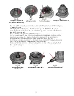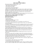
Repairing the Wheel Rim and Changing the Spokes
The required tool is the wrench for driving in spoke nipples. If cracks or dents on the rim are
evident, replace it. Proceed in the following order:
- Using the wrench, turn all the nipples from the spokes, take the spokes out, and inspect them.
Replace defective spokes and nipples;
- Insert 20 short spokes into the drum rim, put the hub on the workbench with the drum facing
down. Arrange the spokes towards the axes of holes in such a way that the spokes intersect at
approximately one half of their length;
- Lay the wheel rim on the workbench with
the hub in the center of the rim; see that the holes for
nipples, which are relatively more declined from the axis of symmetry, are facing down. Arrange
the rim so that the holes for the short spoke nipples coincide with the direction of the spoke axes
(between the intersecting short spokes there should be one hole for the long spoke, directed to
the right);
- Insert the nipples into the rim holes and drive them
on the spokes for about
3/4
of the thread
length;
- Drive the nipples on ten long spokes (three or four turns of the thread) and insert them into the
rim holes arranged between the nipples of intersecting short spokes, slide the spoke heads into
the holes on the hub smaller flange from the outside (the head of installed spoke should lie on the
inside of the flange facing the drum) and drive the nipples to about
3/4
of the thread length;
- Drive the nipples on the ten remaining long spokes, inserting them into the unoccupied holes
and sliding the spoke heads into the holes in the hub flange from the inside (the heads of in-
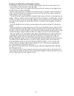
stalled spokes should lie on the outside hub). For general layout of spokes refer to Fig. 35.
Having installed the spokes, turn on all the nipples uniformly and tension the spokes. Check the
reinstalled rim for radial and side run-out, also its proper position relative to the wheel hub.
Tolerated radial and side run-out of the wheel rim should be within 1.5 mm. The outer side
surface of the rim should be positioned at a distance of 5.5
-
7.5 mm from the wheel hub end
face with splines for joining to the final drive.
Having tensioned the spokes and centered the wheels, file all the protruding spoke ends flush
with the nipple heads.
The centering of wheels has to be checked also when only separate broken or bent spokes have
been replaced, making sure that the tension of the replaced spokes is the same as that of the rest
of them. Tighten up other loose spokes revealed.
84
Summary of Contents for 750cc Series
Page 1: ...Repair Manual 750cc All Models www imz ural com ...
Page 2: ......
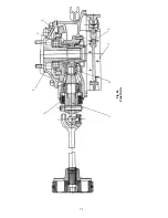
Page 71: ...1 2 3 4 5 6 7 8 Fig 66 Final drive 71 ...
Page 98: ...Fig 11 iring Diagram 9 W 98 ...

