

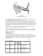

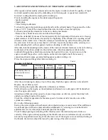


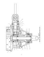


Fig.63
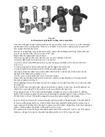
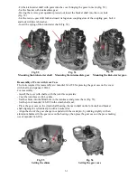
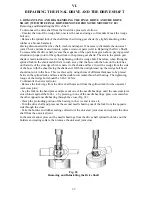
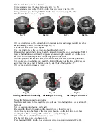
Fig.64
1
2
After full disassembly of the gearbox or repair of the gearshift mechanism, adjust the latter by
turning the clutch shaft with a special crank handle 346-403 (Fig. 63).
To adjust proceed as follows (Fig. 63):
- Undo four screws Mõ5 and remove the right hand cover of the gearbox, covering the shaft of
the quadrant.
- Screw in one of the M5 screws with flat washer to fix the bushing of quadrant shaft.
To adjust the lower stop “A” limiting the turn of the quadrant when up-shifting
(acceleration), proceed as follows (see Fig. 63):
- Depressing the upper arm of the pedal, engage the quadrant in the position of II gear, the
retaining roller should fully get into the flute on the quadrant and lock it in the Pos. 1 (Fig. 63)
by means of the spring(Fig.63).
- Depressing the pedal once again, engages the III gear.
- When the lower stop is adjusted correctly the quadrant turns to required angle and locks again
in Pos.2 (Fig. 63)
When the stop is maladjusted the roller after turn would not get into flute, Pos. 3 and 4 (Fig. 63).
It can be easily found by turning the projecting end of the quadrant this or that way using 10-mm
wrench.
To adjust the upper stop “” limiting the turn of the quadrant when down-shifting
(deceleration), proceed as follows:
- Depressing the lower arm of the pedal, shift the quadrant from III gear to II gear, Pos. 5
(Fig.63)
- Check the quadrant shaft for soundness of locking of the roller in the flute of the quadrant,
using 10-mm wrench. When it is not locked properly, the stop is maladjusted, Pos. 7 and 8
(Fig. 63)
Note:
The gearshift mechanism is factory-adjusted. This operation requires skills and should be
proceeded only when major repair or replacements of parts of gear shift mechanism. Should a
gear disengage spontaneously the stops should not be readjusted, as in such a case that very
pinion of the main shaft calls for replacement, whose gear is involved in spontaneous
disengagement.
Adjustment of the position of the neutral gear pick-up.
During operation of the gearbox the position of neutral gear pick-up may be disturbed. Do the
following:
- Shift the gear shift mechanism to neutral position
- Slacken the wire terminal fastening nut and pick-up screw-locking nut (Fig.64, Pos.2).
- Switch the ignition on, and turning the pick-up screw in or out, make the green tell-tale on the
dash board go on, having checked the circuit of the tell-tale before.
Lock the screw and with the nut and secure the pick-up lead terminal.
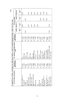
2. REPAIRING THE GEARBOX ASSEMBLY UNITS AND PARTS
When repairing the assembly units and parts of the gearbox, pay special attention to providing
the clearances (positive and negative allowances), keeping in line with values set by the Ma-
nufacturing Works and stipulated in Table 9.
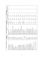
Table 10 gives the tolerated limits of clearances due to wear in the principal mated parts, which
will help to evaluate fitness of separate parts for further service.
63
Summary of Contents for 750cc Series
Page 1: ...Repair Manual 750cc All Models www imz ural com ...
Page 2: ......
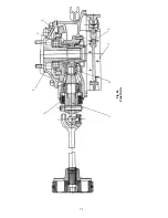
Page 71: ...1 2 3 4 5 6 7 8 Fig 66 Final drive 71 ...
Page 98: ...Fig 11 iring Diagram 9 W 98 ...


