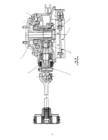


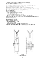


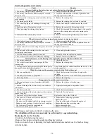


Fig.95
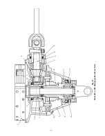
Fig.96
Fig.97
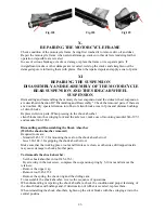
Fig.98
Fig.99
Fig.100
Fig.101
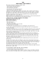
IX .
REPAIRING THE FRONT FORK
S
1. DISMANTLING AND REASSEMBLING THE FRONT FORK
It is possible to partially dismantle or repair the front fork without taking the entire assembly off
the motorcycle.
Removing and reinstalling the front fork leg
(With the front wheel removed, the front fork remaining on the motorcycle)
To dismantle the front fork leg:
- Remove the front feneder when it is fastened to the fork leg tips;
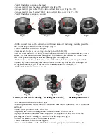
- Unscrew the coupling nut tightening the fork leg tube to the cross-piece (Fig. 95)
- Remove the spring of the front fork (Fig. 96-97). Remove the distance bushing and the spring
when it concerns single bikes.
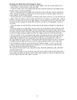
- Loosen the coupling bolt fastening the legs to the front fork bridge
- Remove the fork leg. For easier operation do the nut into the front fork tube for
4-
5 turns
hammer out the tube from the crosspiece cone using a rubber hammer.
- Reverse the sequence of operations to reassemble the front fork. Whilst tightening the nut to
provide the tight sit of the cone in the fork crosspiece, loosen the nut of the coupling bolt first
and tighten it after the tightening of the clamp nut.
Dismantling and Reassembling the Fork Leg
- Drain oil
- Remove the through bolt of the wheel (Fig. 98)
- Remove the screw fastening the shock absorber (Fig. 99)
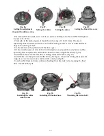
- Remove the shock absorber (Fig. 102 and 103)
- Remove the front fork leg tip (Fig. 100)
- Remove the outer seal (Fig. 101)
- Remove the lock ring (Fig. 104)
- Remove the inner seal (Fig. 104)
Wash and inspect all the removed assembly units and parts, replace defective ones, if necessary.
To reassemble the fork leg, reverse the sequence of the operations.
The priming capacity of the fork leg is 180 cc (SAE 10).
85
Summary of Contents for 750cc Series
Page 1: ...Repair Manual 750cc All Models www imz ural com ...
Page 2: ......
Page 71: ...1 2 3 4 5 6 7 8 Fig 66 Final drive 71 ...
Page 98: ...Fig 11 iring Diagram 9 W 98 ...


