


-
Remove the return spring and ratchet crank from the shifting mechanism.
- Moving the quadrant shaft to the left take out the shaft from the gearbox cover;
- Remove the plate from the quadrant shaft and take the splint out of the quadrant.
Wash the dismantled parts and inspect thoroughly, paying attention to accurate fitting of pin,
pawl axle and the pawl. Check the ratchet and pawl for possible defects, also condition of the
"working edges of the oil seal. Pay special attention to the shift quadrant (check it for wear,
cracks, curvatures, etc.). Replace all the defective parts.
The pawl should pivot freely on its axle, but without any excessive play. The crank arm and pin
should not display an excessive play either, the permissible clearance between them being 0
.
6
mm, maximum.
To reassemble the gearshift mechanism, reverse the sequence of operations, lubricate the friction
surfaces of parts with motor oil. Pay special attention to correct fitting of the return spring and to
proper position of the pawl crank arm on the gear change pedal shaft as well as to safe fastening
of the shaft nut. When correctly assembled, the return spring should be able to return the foot
pedal into the initial position with ease and should have no play in this position. Installing the
lock ring onto the quadrant shaft be sure that the clearance between the lock ring and shims is in
the range of 0
.
1
-
0
.
4 mm. Use Locktite mounting the cover enclosing the right hand end of the
shaft.
For the sequence of disassembly and reassembly of the mechanism refer to Sections "Removing
the Gear Shift Mechanism" and "Reassembly of the Gear Case Cover".
Gearshift forks.
Having removed the forks inspect them and replace, if excessive wear is
revealed (refer to Table 11).
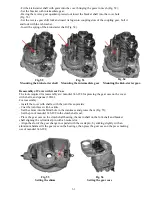
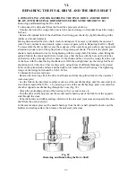
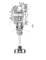
Repairing the Gearbox Shafts
Clutch shaft.
Required tools and fixtures are:
- Puller 345-330-3 for removing the roller bearing cone from the clutch shaft;
- Puller 345-441-3 for pressing-out the clutch roller bearing cup.
Having removed the clutch shaft from the gearbox, wash it and inspect thoroughly. Check
condition of bearings, gear teeth (wear, scores, pitting), the tightness of the IV gear fit, and
condition of splines.
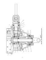
If any defects are revealed, dismantle the clutch shaft as follows using tools 345-330-3 and 345-
659-3:
- Remove the roller bearing cone, using tool 345-659-3
- Use tool 645-659 to press off the gear.
Replace all the defective parts and reassemble in the reverse-order.
When pressing-in the gear, the bearing and the sleeve, make-sure that the gear is fitted with its
flat end towards the shaft shoulder. Lay a rubber ring between the bearing and the sleeve. Press
in the sleeve with its larger chamfer facing out.
When replacing the roller bearing race, make sure to change the race as well which is pressed
into the clutch shaft rear bearing housing. Use puller 345-441-3 for pressing-out the race of the
roller bearing.
When pressing-in the roller bearing race, make sure that its-end face with the mark of the
Manufacturing Works is facing out.
In case the clutch shaft is correctly assembled, the mounting-size measured along the outer faces
of both bearings should be within 134 to 133
.
39 mm.
Main shaft.
Having removed the main shaft, dismantle it and wash all the parts properly. Check
condition of all the parts, paying special attention to the wear of friction surfaces, condition of
teeth of the speed gears, as well as those of the gear engaging sleeves. Replace the defective or
excessively worn-out parts.
Lubricate the main shaft splines with motor oil, when reassembling. Fit the oil baffles with the
bore facing out.
In case of a properly assembled main shaft, mounting size measured along the outer faces of
bushings in the assembled set of gears should be within 106
.
74 to 106
.
264 mm, while the mount-
67
Summary of Contents for 750cc Series
Page 1: ...Repair Manual 750cc All Models www imz ural com ...
Page 2: ......
Page 71: ...1 2 3 4 5 6 7 8 Fig 66 Final drive 71 ...
Page 98: ...Fig 11 iring Diagram 9 W 98 ...


