


345-042-3
345-429-3
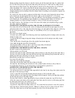
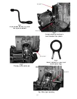
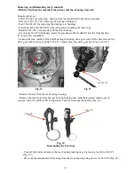
Fig. 12
Removing the clutch plates
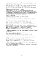
Fig. 13
Removing the flywheel
To reinstall the flywheel:
- Fit the flywheel on the tapered end of the crankshaft; make sure that the rubber seal is correctly
fitted on the flywheel hub and that the key coincides with the keyway in the flywheel hub;
- Fit a lock washer on;
- Install wrench 19õ22;
- Tighten up reliably the flywheel fastening bolt using wrench 348-801, the tightening torque
being 216
-
245 Nm
- Bend over the head of the lock washer to cover one of the bolt faces;
- Remove wrench 19Õ22.
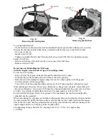
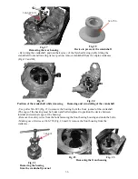
Removing and Reinstalling the Oil Pump
(with the engine removed and set up on a mounting stand)
To remove the oil pump:
- Drain oil from the engine crankcase through the drain hole in the sump;
- Undo the plug of the oil pump drive and remove the drive gearing;
- Undo the screws fastening the engine sump; remove the sump together with the gasket;
- Uncotter and take off the pump filter;
- Turn off two bolts fastening the pump and remove the oil' pump together with the bar (assy).
Wash and inspect the pump. If necessary, dismantle it, change worn-out parts, reassemble and
check its performance. At a speed of 670 rpm the oil pump should develop a pressure of at least
0.4 MPa . Use spindle oil grade B3 for this test. The pump delivery is 80 to 100 1/h.
To reinstall the oil pump, reverse the sequence of the operations, having first reinstalled the
crankshaft and the camshaft.
When remounting the oil pump, see that the sealing gasket does not overlap the oil duct and that
the pump casing fits tightly the thrust surface, also see that the drive shaft rod enters the square
hole of the drive gear. Having reinstalled the oil pump, proceed directly with remounting of the
engine sump and screw on the plug of the oil pump drive.
The tightening torque should be for: oil pump
bolt 15.7
-
17.6 Nm ; for engine sump
7.8
-
9.8Nm .
34
Summary of Contents for 750cc Series
Page 1: ...Repair Manual 750cc All Models www imz ural com ...
Page 2: ......
Page 71: ...1 2 3 4 5 6 7 8 Fig 66 Final drive 71 ...
Page 98: ...Fig 11 iring Diagram 9 W 98 ...


