4.- PREPARATIONS BEFORE TO USE
- 23 -
4.2.- Equipment connection
In view of danger that this equipment misuse might entail,
ALWAYS
ADHERE TO THE SEQUENCE DESCRIBED BELOW.
For the performance of a test, the measuring unit and control computer should be
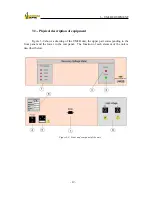
located close to the equipment to be analyzed, as shown in Figure 4-1. To start up the
equipment, carry out the following instructions in the order presented (the different elements
of the panels in Figure 3-9 are referred to in brackets):
Figure 4-1: Disposition of the test elements.
- Connection of PC to UM2B.
This connection is accomplished with the series cable, connected to the serial
communications port of the PC.
Summary of Contents for UM2B
Page 2: ......
Page 67: ...5 SOFTWARE DESCRIPTION 65 Figure 5 46 a First page of the report Recovery Voltage ...
Page 68: ...5 SOFTWARE DESCRIPTION 66 Figure 5 47 a Second page of report Recovery Voltage ...
Page 69: ...5 SOFTWARE DESCRIPTION 67 Figure 5 48 Third page of report Recovery Voltage ...
Page 70: ...5 SOFTWARE DESCRIPTION 68 Figure 5 46 b First page of the report Insulation Resistance ...
Page 71: ...5 SOFTWARE DESCRIPTION 69 Figure 5 47 b Second page of the report Insulation Resistance ...
Page 87: ...8 TECHNICAL SUPPORT 85 Description of fault Materials returned on of of the year Table 8 1 ...
Page 95: ...APPENDIX B CONTROL SOFTWARE 93 APPENDIX A CE CONFORMITY DECLARATION ...

