5.- SOFTWARE DESCRIPTION
- 40 -
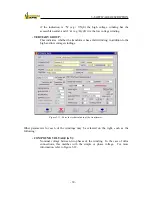
Figure 5-12: Diagram of simple/compound voltage.
- CURRENT (A):
Nominal current of the winding.
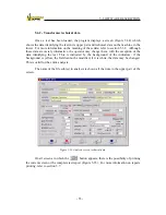
There is also a list-type selection box which indicates whether the winding has a
regulator, and adjuster or neither. If the winding has a regulator/adjuster, there will be an
additional series of parameters:
- TYPE:
Model of regulator/adjuster. This is defined on the nameplate.
- MANUFACTURER:
Name of regulator/adjuster manufacturer.
- N. OF OPERATIONS:
Number of times that the position of the transformer regulator has been
modified in operation (modifications undergone during test performance do
not count).
- REGULATION:
Type of regulator. May be under load, a switching regulator or under cover.
- No OF POSITIONS:
Number of regulations positions of the regulator/adjuster.
- STEP:
Increase in magnitude between one position and the next. This may be
defined in volts or in percentage terms (%), with respect to the rated voltage.
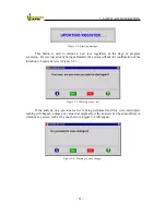
If define in percentage terms (%), the increase may not exceed 100; if this
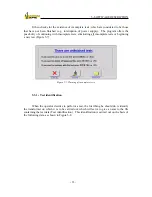
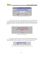
occurs, an error message appears (Figure 5-13).
Summary of Contents for UM2B
Page 2: ......
Page 67: ...5 SOFTWARE DESCRIPTION 65 Figure 5 46 a First page of the report Recovery Voltage ...
Page 68: ...5 SOFTWARE DESCRIPTION 66 Figure 5 47 a Second page of report Recovery Voltage ...
Page 69: ...5 SOFTWARE DESCRIPTION 67 Figure 5 48 Third page of report Recovery Voltage ...
Page 70: ...5 SOFTWARE DESCRIPTION 68 Figure 5 46 b First page of the report Insulation Resistance ...
Page 71: ...5 SOFTWARE DESCRIPTION 69 Figure 5 47 b Second page of the report Insulation Resistance ...
Page 87: ...8 TECHNICAL SUPPORT 85 Description of fault Materials returned on of of the year Table 8 1 ...
Page 95: ...APPENDIX B CONTROL SOFTWARE 93 APPENDIX A CE CONFORMITY DECLARATION ...


