6.- EQUIPMENT MAINTENANCE
- 77 -
3.
Check the continuity between cable ends. We take the high voltage's connector that
goes into the UM2B unit and the clip of the other cable end. We place one
multimeter test tips in contact with the connector's interior tip (active) and the other
multimeter test tips in contact with the clamp that is in the other cable end. The
multimeter should say continuity.
Figure 6-2: Continuity check between cable ends.
4.
Previous checks could be performed by the user, but it should also be checked
dielectric rigidity and insulation resistance of the cable should they be damaged. This
two last verifications only could be performed by the technical service.
Summary of Contents for UM2B
Page 2: ......
Page 67: ...5 SOFTWARE DESCRIPTION 65 Figure 5 46 a First page of the report Recovery Voltage ...
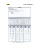
Page 68: ...5 SOFTWARE DESCRIPTION 66 Figure 5 47 a Second page of report Recovery Voltage ...
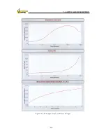
Page 69: ...5 SOFTWARE DESCRIPTION 67 Figure 5 48 Third page of report Recovery Voltage ...
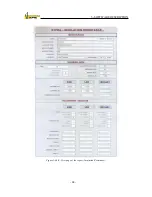
Page 70: ...5 SOFTWARE DESCRIPTION 68 Figure 5 46 b First page of the report Insulation Resistance ...
Page 71: ...5 SOFTWARE DESCRIPTION 69 Figure 5 47 b Second page of the report Insulation Resistance ...
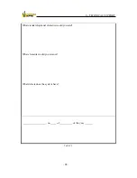
Page 87: ...8 TECHNICAL SUPPORT 85 Description of fault Materials returned on of of the year Table 8 1 ...
Page 95: ...APPENDIX B CONTROL SOFTWARE 93 APPENDIX A CE CONFORMITY DECLARATION ...


