5.- SOFTWARE DESCRIPTION
- 49 -
To initiate measurement, click on the
button, and, in case the high or low
voltage of the machine (in function in the connection mode) is inferior than the test voltage
selected by the user, the following warning message will be shown (Figure 5-20):
Figure 5-20: Warning message.
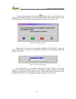
Subsequently, the program will undertake calibration of the UM2B, showing the
message that appears in Figure 5-21 throughout the process. The indicator bar shows the
time last in seconds.
Figure 5-21: Calibration message.
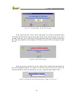
In case the machine is not completely discharged, the unit will detect it, and it will
warn the user with the following message, giving option to discharge it (Figure 5-22). If this
discharge is not performed, the graph of recovery voltage could result altered from the one
that should be drawn, most of all appearing a higher voltage in the first cycles.
Summary of Contents for UM2B
Page 2: ......
Page 67: ...5 SOFTWARE DESCRIPTION 65 Figure 5 46 a First page of the report Recovery Voltage ...
Page 68: ...5 SOFTWARE DESCRIPTION 66 Figure 5 47 a Second page of report Recovery Voltage ...
Page 69: ...5 SOFTWARE DESCRIPTION 67 Figure 5 48 Third page of report Recovery Voltage ...
Page 70: ...5 SOFTWARE DESCRIPTION 68 Figure 5 46 b First page of the report Insulation Resistance ...
Page 71: ...5 SOFTWARE DESCRIPTION 69 Figure 5 47 b Second page of the report Insulation Resistance ...
Page 87: ...8 TECHNICAL SUPPORT 85 Description of fault Materials returned on of of the year Table 8 1 ...
Page 95: ...APPENDIX B CONTROL SOFTWARE 93 APPENDIX A CE CONFORMITY DECLARATION ...


