3.- UM2B EQUIPMENT
- 20 -
1
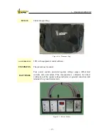
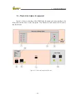
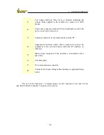
Test voltage indicator. This acts as a voltmeter, indicating the
voltage being applied to the machine by means of 4 LED
diodes.
2
Power unit connection indicator. This should light up when the
power switch (4) is turned on.
3
Luminous indicator of communications with the PC.
4
Equipment connection switch. This is operated to connect the
equipment to the electrical mains when the PC software so
indicates.
5
Mains input connection. This includes a fuse-holder and a
spare fuse.
6
Unit nameplate.
7
PC communications connector.
8
Connectors for high voltage cables running to equipment being
tested.
The rest of the indicators / warnings appear on the computer screen and will be
described in detail in chapter 5 (
Software description
).
Summary of Contents for UM2B
Page 2: ......
Page 67: ...5 SOFTWARE DESCRIPTION 65 Figure 5 46 a First page of the report Recovery Voltage ...
Page 68: ...5 SOFTWARE DESCRIPTION 66 Figure 5 47 a Second page of report Recovery Voltage ...
Page 69: ...5 SOFTWARE DESCRIPTION 67 Figure 5 48 Third page of report Recovery Voltage ...
Page 70: ...5 SOFTWARE DESCRIPTION 68 Figure 5 46 b First page of the report Insulation Resistance ...
Page 71: ...5 SOFTWARE DESCRIPTION 69 Figure 5 47 b Second page of the report Insulation Resistance ...
Page 87: ...8 TECHNICAL SUPPORT 85 Description of fault Materials returned on of of the year Table 8 1 ...
Page 95: ...APPENDIX B CONTROL SOFTWARE 93 APPENDIX A CE CONFORMITY DECLARATION ...


