3.- UM2B EQUIPMENT
- 10 -
The UM2B unit is designed to output a direct current voltage of up to 2 kV to the
element to be tested, carry out the loading and discharge intervals on the dielectric as
described for the specific test and, finally, measure the voltage and current.
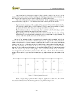
The unit will examine the status of the dielectric of the equipment being tested, as
shown electrically in figure 2.1. The different elements in this figure are as follows:
-
Cg
, Geometric capacity of the equipment being tested. This will be determined by
the physical characteristics of the armatures of the equivalent condenser, surface,
properties of intermediate dielectric and separation between armors.
-
Ra
, Insulation resistance. In measuring, this is related to the final leakage current
following the transitory loading period of the dielectric.
-
Rpx and Cpx
are the electrical elements used to describe the recovery voltage
characteristic. In an equivalent circuit there will be a multitude of such elements, in
order to reflect the distributed nature of this behavior.
The test to be performed aims to determine the equivalent time constants Rp/Cp, the
measure and evolution of which are determining factors as regards the current and future
status of the dielectric. The test consists of inserting over a time T a previously established
voltage of up to 2 kV. Following this time, a short-circuit is performed on the sample for a
time T/2, and finally the evolution of the recovery voltage appearing is recorded. This
process (cycle) is repeated for multiples of T, and the maximum recovery voltages associated
with each interval or cycle are used to graph a curve on which would be shown in a T time
axis of application and maximum tension in the other axis. Above the mentioned dots a
fitting curve is drawn. Then, each time constants Rp/Cp should appear as a maximum on the
graph.
Figure 2.1: Dielectric equivalent circuit.
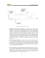
When a high voltage generator DC voltage is applied to a dielectric, the current
across the insulation shows the following behavior, as plotted in figure 2-2.
Summary of Contents for UM2B
Page 2: ......
Page 67: ...5 SOFTWARE DESCRIPTION 65 Figure 5 46 a First page of the report Recovery Voltage ...
Page 68: ...5 SOFTWARE DESCRIPTION 66 Figure 5 47 a Second page of report Recovery Voltage ...
Page 69: ...5 SOFTWARE DESCRIPTION 67 Figure 5 48 Third page of report Recovery Voltage ...
Page 70: ...5 SOFTWARE DESCRIPTION 68 Figure 5 46 b First page of the report Insulation Resistance ...
Page 71: ...5 SOFTWARE DESCRIPTION 69 Figure 5 47 b Second page of the report Insulation Resistance ...
Page 87: ...8 TECHNICAL SUPPORT 85 Description of fault Materials returned on of of the year Table 8 1 ...
Page 95: ...APPENDIX B CONTROL SOFTWARE 93 APPENDIX A CE CONFORMITY DECLARATION ...


