APPENDIX B: ELECTRICAL AND DATA CONNECTIONS
HF25D DC RESISTANCE WELDING SYSTEM
B-10
990-333
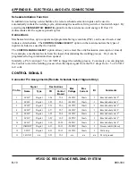
Schedule Initiation Function
In addition to selecting weld schedules, the remote schedule selection inputs can be used to
automatically initiate the welding cycle, eliminating the need for a firing switch or foot switch input. By
selecting the
FIRING SWITCH: REMOTE
option from the main menu, weld energy will flow 20
milliseconds after the squeeze period expires.
Connections
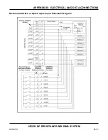
Mechanical switches, opto couplers and programmable logic controls (PLC) can be used to select and
initiate weld schedules. The
CONTROL SIGNAL SELECT
: option on the main menu lists the types of
input switch devices used by the Control.
The
CONTROL SIGNAL SELECT
: option allows you to select the switch actuation state (open or closed).
For example, a mechanical switch can be closed, thus initiating the welding process. Or, it can be
programmed to begin initiation when opened.
Similarly, a PLC can input +5 to +24 VDC to trigger the welding process. Conversely, you can program
the Control to start the welding process when the input signal from the PLC drops from +5 or 24 VDC
to 0 volts.
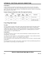
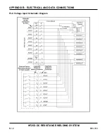
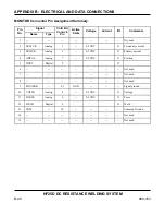
CONTROL SIGNALS
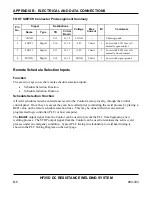
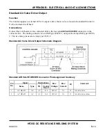
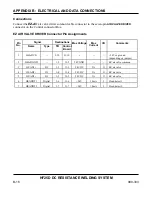
Connector Pin Assignments (Remote Schedule Select Signals Only)
Signal Destinations
Pin No.
Name Type TB
Control
Board
Max
Voltage
Max
Current
I/O Comments
1 SCH2
0
Digital
3-24
J2-4
+24VDC
10mA
I
Rem Schedule Sel 2
0
2 SCH2
1
Digital
3-25
J2-5
+24VDC
10mA
I
Rem Schedule Sel 2
1
3 SCH2
2
Digital
3-26
J2-6
+24VDC
10mA
I
Rem Schedule Sel 2
2
4 SCH2
3
Digital
3-27
J2-7
+24VDC
10mA
I
Rem Schedule Sel 2
3
12 SCH2
4
Digital
3-28
J2-8
+24VDC
10mA
I
Rem Schedule Sel 2
4
5 SCH2
5
Digital
3-29
J2-9
+24VDC
10mA
I
Rem Schedule Sel 2
5
14 SCH2
6
Digital
3-30
J2-10
+24VDC
10mA
I
Rem Schedule Sel 2
6
9
INHIBIT
Digital
4-31
J2-11
+24VDC
10mA
I
Process inhibit (Reset)
10 STOP Digital 4-32 J2-12
+24VDC
10mA I Weld
stop
11
24GND
n/a
3-23
J2-3
n/a
n/a
n/a
24 volt ground
Summary of Contents for HF25A
Page 9: ...HF25D DC RESISTANCE WELDING SYSTEM 990 333 ix ...
Page 10: ......
Page 20: ......
Page 84: ...CHAPTER 6 CALIBRATION HF25D DC RESISTANCE WELDING SYSTEM 990 333 6 4 Final Calibration Setup ...
Page 113: ......
Page 129: ......
Page 153: ......
Page 171: ......

