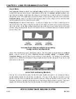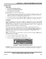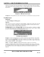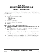
CHAPTER 4. OPERATING INSTRUCTIONS
HF25D DC RESISTANCE WELDING SYSTEM
990-333
4-3
Section II. Programming Weld Schedules
Introduction
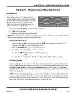
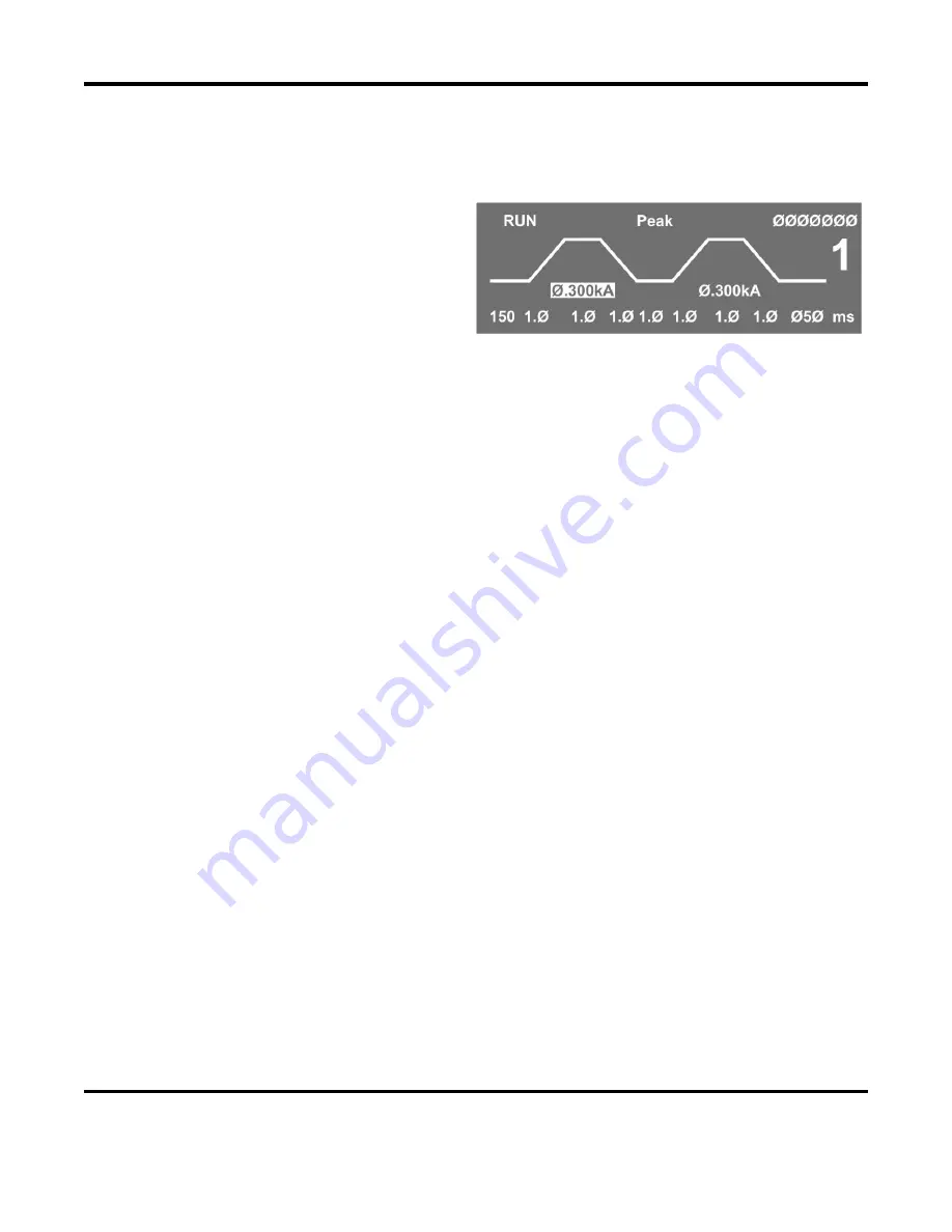
The Control comes with 99 factory-installed
weld schedules, numbered from
01
through
99
.
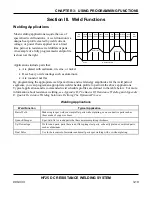
Each schedule looks like the display on the right.
See
Section III, Using HF25 Welding And
Monitoring Functions
for descriptions of the
features available in weld schedules.
The process of
Programming
a weld schedule consists of:
•
Select
a weld schedule.
•
Enter
new values in the selected schedule.
NOTE:
For reference and convenience, you might want to keep a written list of your programmed weld
schedule values using the two-digit weld schedule number.
Select A Weld Schedule
1.
To select weld schedules, first make sure that the
RUN
state is displayed on the LCD. If
not, press the
RUN
key on the front of the Control.
2.
Press the
SCHEDULE
key on the right of the Control.
3.
Use
either
of the methods below to select a schedule:
•
Use the
VW
(Up/Down) keys to scroll through the list.
OR
•
Use the numeric keypad to enter the two-digit number of the schedule you want.
Enter New Values
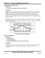
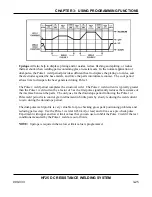
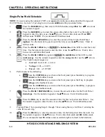
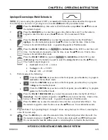
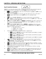
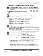
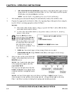
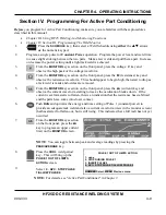
Some welding applications require no more than a simple weld schedule, programmed for Single-
Pulse, Upslope/Downslope, or Dual-Pulse operation. For other applications, you may want to use
the
Energy Limits Monitor
or
Active Part Conditioning
features of the Control. To
enter new
values
, follow the instructions for Single-Pulse, Upslope/Downslope, or Dual-Pulse weld schedules
on the following pages.
NOTE:
If drastically different energy values are entered for Pulse 1 and Pulse 2, the Control will
require a minimum of 0.5 ms Cool Time. If different feedback modes are programmed for a dual
pulse weld, the Control will require a minimum of 0.5 ms Cool Time. If a Cool Time is set lower
than 0.5 ms, but not zero, the Control will default to 0.5 ms Cool Time.
Summary of Contents for HF25A
Page 9: ...HF25D DC RESISTANCE WELDING SYSTEM 990 333 ix ...
Page 10: ......
Page 20: ......
Page 84: ...CHAPTER 6 CALIBRATION HF25D DC RESISTANCE WELDING SYSTEM 990 333 6 4 Final Calibration Setup ...
Page 113: ......
Page 129: ......
Page 153: ......
Page 171: ......

