HF25D DC RESISTANCE WELDING SYSTEM
990-333
B-1
APPENDIX B
ELECTRICAL AND DATA CONNECTIONS
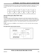
Electrical Connection
As described in
Chapter 2
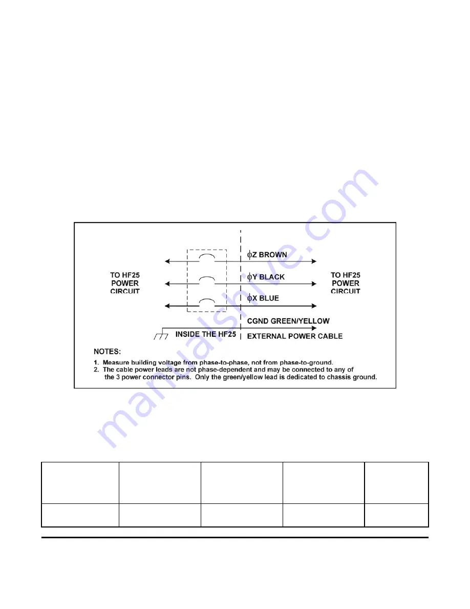
, you need to supply a connector for the Control input power cable (refer to
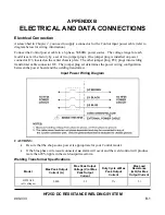
diagram below for wiring information).
Connect the Control power cable to a 3-phase, 50/60Hz power source. The voltage range for each
model is set at the factory by a set of two jumper plugs. One jumper plug is installed on power
connector J23, located on the center chassis plate. The other jumper plug, P22, plugs into welding
transformer cable connector J22. The jumper plug set determines the power wiring configuration
between the power board and the welding transformer.
Input Power Wiring Diagram
CAUTIONS:
•
Be sure that the shop source power is appropriate for your Control model.
•
If the blue phase wire is
not
connected,
no
alarm will occur and the weld control will produce
more than 20% ripple in the weld output waveform.
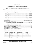
Welding Transformer Specifications
Model
Max Peak Output
Current (A)
Max Peak Output
Voltage (V) at Max
Peak Output
Current
Duty Cycle at Max
Peak Output
Current
Max Load
Resistance
(m
Ω
) for Max
Output Current
HF25A10
(all voltages)
2,400 5.2 3%
2.1
Summary of Contents for HF25A
Page 9: ...HF25D DC RESISTANCE WELDING SYSTEM 990 333 ix ...
Page 10: ......
Page 20: ......
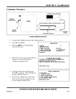
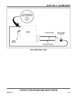
Page 84: ...CHAPTER 6 CALIBRATION HF25D DC RESISTANCE WELDING SYSTEM 990 333 6 4 Final Calibration Setup ...
Page 113: ......
Page 129: ......
Page 153: ......
Page 171: ......

