CHAPTER 4. OPERATING INSTRUCTIONS
HF25D DC RESISTANCE WELDING SYSTEM
990-333
4-11
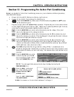
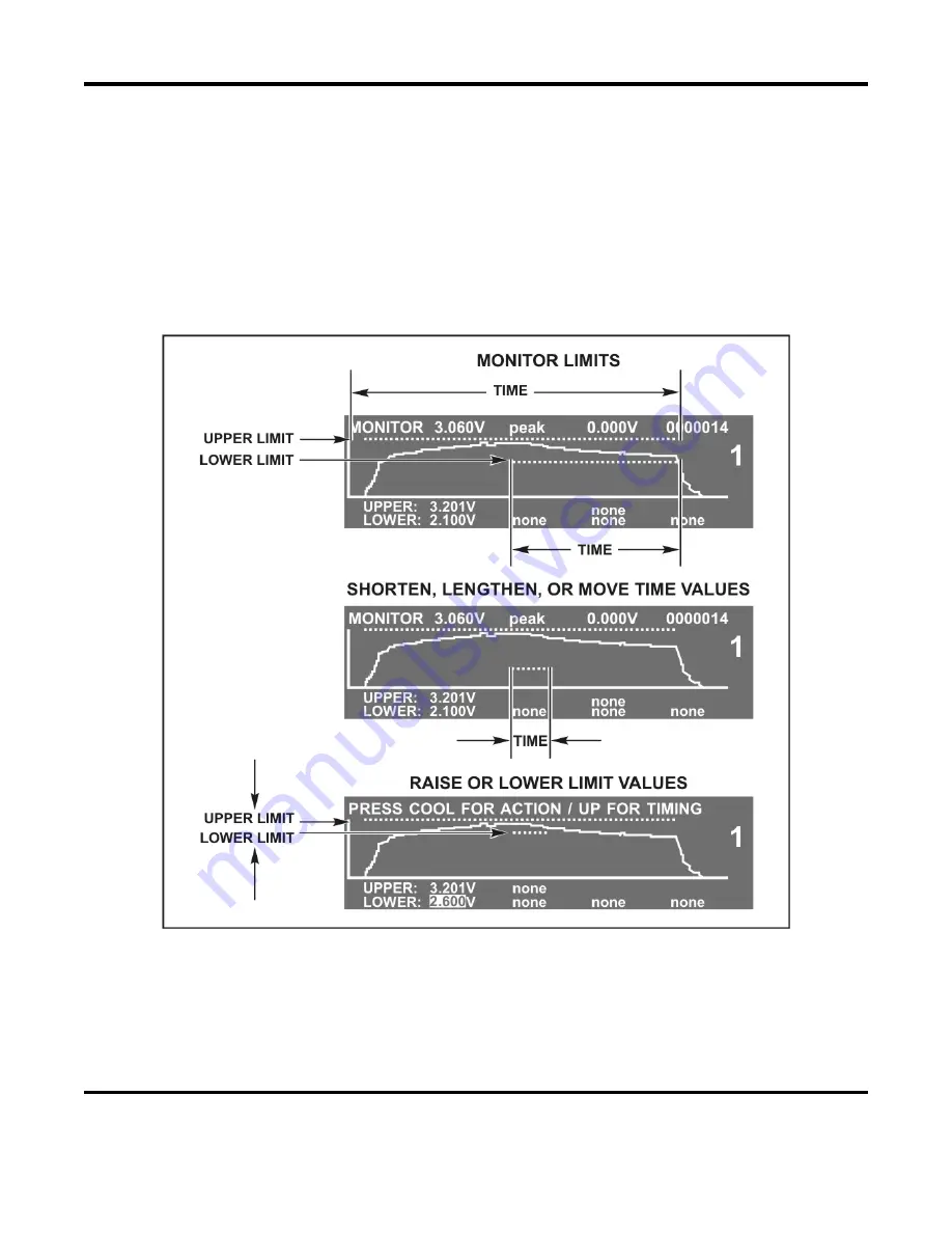
Section V. Adjusting Monitor Limit Values
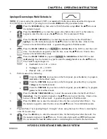
The Control allows you to adjust extremely precise limits for the amount of energy and weld time. Like
all welding processs development, you’ll need to make several test welds, and view the waveforms and
limits of actual welds in order to “fine tune” the limits to your needs.
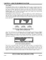
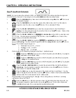
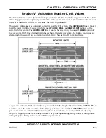
The energy limits appear as horizontal dotted lines on the LCD screen. The
UPPER LIMIT
line is longer
than the lower limit line because it includes the
UPSLOPE
,
WELD
, and
DOWNSLOPE
portions of the
actual weld waveform. The
LOWER LIMIT
line is shorter because it only includes the
WELD
portion of
the waveform. If the line of either limit crosses the weld energy waveform, the Control can trigger an
alarm, inhibit the second pulse, or stop the weld energy. See Section III for more details.
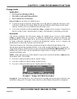
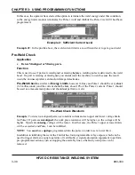
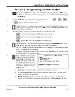
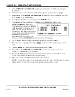
As you can see by the LCD screens above, you can shorten the length of the time of the
LOWER LIMIT
so
it will not cross the weld waveform. This allows you to raise or lower the
LOWER LIMIT
closer to the
peak of the actual waveform
without
crossing the weld waveform. For some welds it may be very
important to get up to the peak voltage or current to get the right melting and get there at the right time
during the pulse. Every millisecond could be very important.
Summary of Contents for HF25A
Page 9: ...HF25D DC RESISTANCE WELDING SYSTEM 990 333 ix ...
Page 10: ......
Page 20: ......
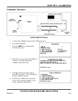
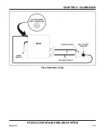
Page 84: ...CHAPTER 6 CALIBRATION HF25D DC RESISTANCE WELDING SYSTEM 990 333 6 4 Final Calibration Setup ...
Page 113: ......
Page 129: ......
Page 153: ......
Page 171: ......