

CHAPTER 4. OPERATING INSTRUCTIONS
HF25D DC RESISTANCE WELDING SYSTEM
4-12
990-333
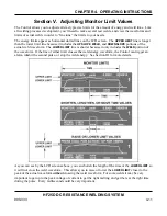
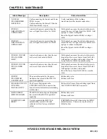
1.
Set an
UPPER LIMIT
and
LOWER LIMIT
using the procedures in
Section III, Programming the
Weld Monitor.
2.
Perform a weld to see how the limits (dotted lines) appear compared to the weld graph.
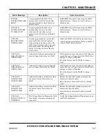
3.
Raise or lower the
UPPER LIMIT
and
LOWER LIMIT
as necessary using the procedures in
Section
III, Programming the Weld Monitor
.
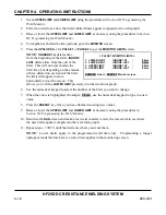
4.
To lengthen or shorten the time periods, go to the
MONITOR
screen.
5.
Press the
UPSLOPE
key for
PULSE 1
or
PULSE 2
to get the
MONITOR LIMITS
screen.
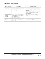
NOTE:
INGNORE 1st
deletes time
from the beginning of the limit,
IGNORE
LAST
deletes time from the end of the
limit. This will not only shorten the
limit time, but depending on the amount
of time deleted on each end of the limit,
the limit will appear to move
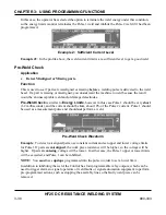
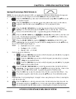
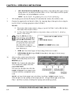
< PULSE 1 MONITOR LIMITS >
1. LOWER LIMIT
IGNORE 1ST
:
0.0ms
2. LOWER LIMIT
IGNORE LAST :
2.5ms
3. UPPER LIMIT
IGNORE 1ST
:
0.0ms
4. UPPER LIMIT
IGNORE LAST :
0.0ms
NUMBER Select, ENERGY Monitor screen
horizontally across the screen. This
allows you to fit the
LOWER LIMIT
precisely into the waveform graph.
6.
Use the numerical keypad to select the number of the limit you want to change.
7.
When the value is highlighted (Example:
2.5ms
), use the numerical keypad to type in a new
value.
8.
Press the
ENERGY
key when you have finished entering new values.
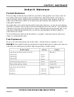
9.
Raise or lower the
UPPER LIMIT
and
LOWER LIMIT
as necessary using the procedures in
Section III, Programming the Weld Monitor
.
10.
Return to the
RUN
screen and make a test weld in order to view the waveform to see where
the new limits appear compared to the waveform graph.
11.
Repeat steps 1
£
10 until the limits are where you want them.
NOTE:
Lower limits apply to the programmed weld time only. Programming a longer
upslope extends the time before a lower limit applies in the monitoring screen.
Summary of Contents for HF25A
Page 9: ...HF25D DC RESISTANCE WELDING SYSTEM 990 333 ix ...
Page 10: ......
Page 20: ......
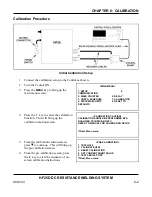
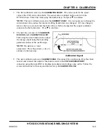
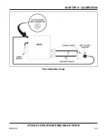
Page 84: ...CHAPTER 6 CALIBRATION HF25D DC RESISTANCE WELDING SYSTEM 990 333 6 4 Final Calibration Setup ...
Page 113: ......
Page 129: ......
Page 153: ......
Page 171: ......


