


APPENDIX E. COMMUNICATIONS
HF25D LINEAR DC RESISTANCE WELDING CONTROL
990-333
E-23
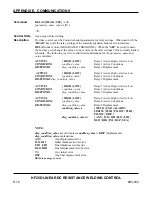
Command
DISP
schedule_number
<crlf>
INITLO {
initial_thick_lo }
<crlf>
INITHI {
initial_thick_hi }
<crlf>
FINALLO {
final_thick_lo }
<crlf>
FINALHI {
final_thick_hi }
<crlf>
DISPLO {
displacement_lo }
<crlf>
DISPHI {
displacement_hi }
<crlf>
DISPWT {
displacement_wtd }
<crlf>
}
UNITS
{ IN/1000 | MM }
<crlf>
INITERR
{ CONT | STOP }
<crlf>
<lf>
Control State
Any except while welding
Description
Reports the current settings of the Control system displacement limit checking parameters.
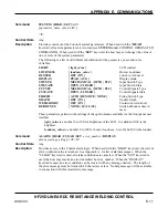
NOTES:
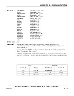
The units of the limit fields parameters depend on the value of the
UNITS
parameter as
follows:
IN/1000:
1 = 0.001 inches; 10 = 0.01 inches
MM:
1 = 0.01 mm; 10 = 0.1 mm
Initial and final thickness are positive if the electrodes move farther apart and negative if they
move closer together (in relation to the “zero setting”). The reference “zero setting” for
thickness measurements may be set using the
DISPZERO
command (see
Host Originated
Commands
section).
Displacement is positive if the electrodes moved closer together during the weld and negative
if they moved further apart.
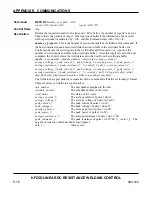
Command
DISPZERO
ad_counts<crlf><lf>
Control State
Any except while welding
Description
Reports the current “zero setting” of the Control system displacement measuring device.
This value is in a/d converter counts (not actual position). If zero, the position of the upper
electrode at the start of the next weld will establish the new zero setting.
NOTE
: This zero setting is the reference position for the initial and final thickness
measurements.
Summary of Contents for HF25A
Page 9: ...HF25D DC RESISTANCE WELDING SYSTEM 990 333 ix ...
Page 10: ......
Page 20: ......
Page 84: ...CHAPTER 6 CALIBRATION HF25D DC RESISTANCE WELDING SYSTEM 990 333 6 4 Final Calibration Setup ...
Page 113: ......
Page 129: ......
Page 153: ......
Page 171: ......


