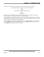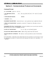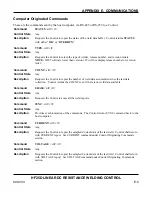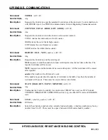
APPENDIX D: LVDT OPTION
HF25 DC RESISTANCE WELDING SYSTEM
D-8
990-333
3
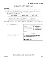
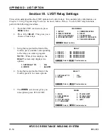
Press
7
to start calibration.
PRE-CALIBRATION
1. TEST HF25 (T-232 REQUIRED)
2. CALIBRATE HF25
3. RESET CALIBRATION
4. SET CURRENT SHUNT VALUE 6. LVDT GAUGE
5. TEST SERIAL PORT
7. CALIB LVDT
NUMBER Select, MENU Previous menu
4
Verify that the electrodes are securely
installed in the electrode holders.
5
Manually adjust the weld head so the
electrodes are touching.
6
Press down on the weldhead force tube
until you hear the microswitch click,
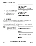
LVDT CALIBRATION
PUT THE ELECTRODES TOGETHER, THEN
PRESS
W
WHEN THEY ARE TOGETHER
MENU Previous menu
then press the
W
button on the front
panel as shown on the screen on the right.
7
Open the electrodes.
8
Insert the calibration gauge of the value
requested between the electrodes.
9
Manually adjust the weld head so the
electrodes are touching the part.
10
Press down on the weldhead force tube
until you hear the microswitch click,
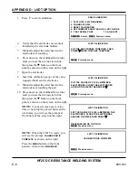
LVDT CALIBRATION
PUT THE GAUGE OF 0.100 in BETWEEN
ELECTRODES, CLOSE THE ELECTRODES
AROUND THE PIECE THEN PRESS
W
MENU Previous menu
then press the
W
button on the front
panel as shown on the screen on the right.
NOTE:
if your reference piece is too
thin, or not properly placed between the
electrodes, you will see the prompt at
the bottom of the screen on the right.
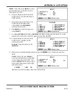
LVDT CALIBRATION
PUT THE GAUGE OF 0.100 in BETWEEN THE
ELECTRODES, CLOSE THE ELECTRODES
AROUND THE PIECE THEN PRESS
W
PIECE MISSING OR TOO THIN
MENU Previous menu
NOTE:
When the LVDT is ready, you
will see the prompt
CALIBRATION IS
COMPLETE
as shown on the right.
Press the
MENU
button on the front
panel to return to the
MAIN MENU
.
LVDT CALIBRATION
CALIBRATION IS COMPLETE
MENU Previous menu
Summary of Contents for HF25A
Page 9: ...HF25D DC RESISTANCE WELDING SYSTEM 990 333 ix ...
Page 10: ......
Page 20: ......
Page 84: ...CHAPTER 6 CALIBRATION HF25D DC RESISTANCE WELDING SYSTEM 990 333 6 4 Final Calibration Setup ...
Page 113: ......
Page 129: ......
Page 153: ......
Page 171: ......

