


5: Parallel UPS System Operating Procedures
44
UPS725-02-02 PowerWave 1000 (4.5 - 10 kVA) User Manual UK Dated 13/03/15
5.1
System start-up procedure
This procedure assumes that the UPS system is being started from a fully shutdown condition and no external
(maintenance) bypass facility is connected.
1. Ensure that all the UPS input circuit breakers located on the rear of the UPS are open (for both utility and bypass
supplies, where separate).
2. Ensure that all load distribution isolators are open, or the individual load items are turned OFF.
3. Ensure that you can identify module 1 in the parallel system – the module set as
ld01
. This should be the bottom-
most or left-most module (See paragraph 3.7.3).
4. On each UPS module in turn
EXCLUDING MODULE 1
–
Turn
ON
the UPS utility input supply (and bypass supply if separate) then
close the input circuit breaker(s) and battery circuit breaker located on the
rear of the enclosures.
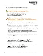
a) The UPS fans will start.
b) The control system will boot-up and initially turn on all the leds and LCD
symbols for a few seconds.
c) Once the control system has booted, the
ECO
and
N+1
leds will
extinguish.
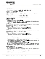
d) The UPS will then carry out some internal self tests.
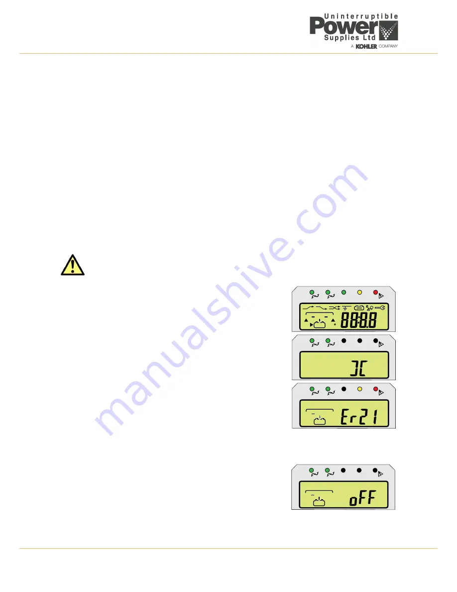
e) When the self tests are completed the LCD screen will display an
Er21
error code.
5. ON MODULE 1 –
Turn
ON
the UPS utility input supply (and bypass supply if separate) then
close the input circuit breaker(s) and battery circuit breaker located on the
rear of the enclosures.
6. Module 1 will boot up in exactly the same manner as described above for the
other models, but at the end of its self checks:
a) It will turn on its static bypass supply and the LCD mimic will indicate the
‘on bypass’ status and the battery being charged.
b) The UPS output status will be shown as
off
.
5
Parallel UPS System
Operating Procedures
CAUTION: The system may malfunction if Module 1 is not the last to be started.
LINE
UPS
LOAD
V
A
%
Hz
C
LOW
?
1
2
EC
O
N+1
1
2
EC
O
N+1
LINE
UPS
LOAD
1
2
EC
O
N+1
LINE
UPS
LOAD
1
2
EC
O
N+
1


