3: Installation and Set-up
36
UPS725-02-02 PowerWave 1000 (4.5 - 10 kVA) User Manual UK Dated 13/03/15
3.8.3 Setting up the basic UPS operating parameters
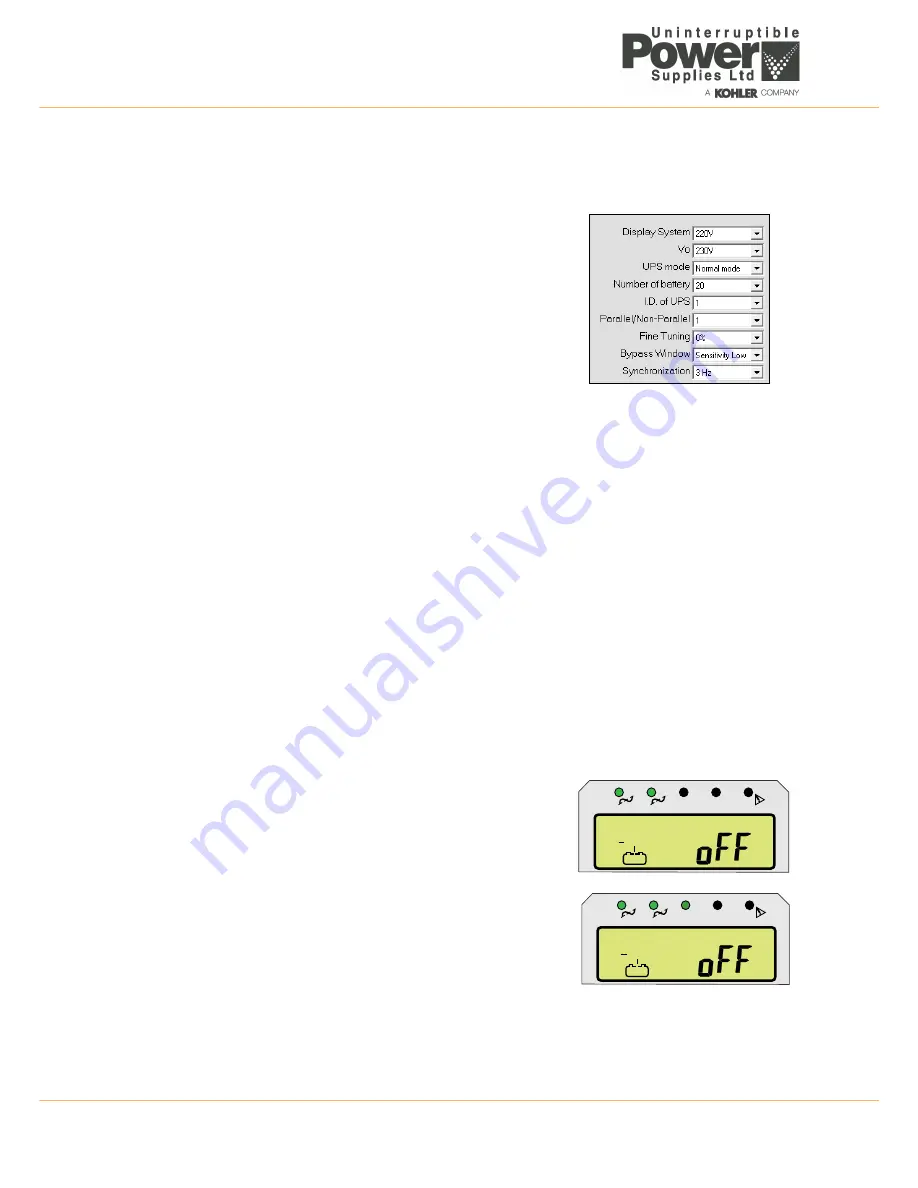
The UPS Setting Tool allows you to set up several basic UPS operating parameters.
1. Select the required parameters using the drop-down selector boxes
(*default):
a)
Display System
voltage selection –
220V
*,
110V.
b)
Vo
(Output voltage selection) –
200V
,
208V
,
220V
*,
230V
,
240V
.
c)
UPS Mode
–
Normal mode*
(50Hz input/output),
CF50
(50Hz/60Hz
input/output),
CF60
(60Hz/50Hz input/output). Note that in a parallel
system
Normal mode
is the only permitted selection.
d)
Number of battery
– number of battery block fitted. If it important
that this is set correctly as it affects the battery charging parameters.
e)
I.D. of UPS
– Set to
01
in a single module installation. In a
parallel system this sets the module identity within the parallel chain.
The module set at
01
is the
master
module, and the remaining
modules must be set to
02
,
03
or
04
respectively.
f)
Parallel/Non-Parallel
– Set to
01
in a single module installation and
02
in a parallel module system.
g) Fine Tuning (Output Voltage) –
+3%
,
+2%
,
+1%
,
0%
*,
-1%
,
-2%
,
-3%
.
h) Bypass Voltage Window –
Sensitivity Low
*,
Sensitivity High
.
i)
Syn-Frequency Window–
3Hz
*,
1Hz
.
2. Once all the parameters have been selected, click the
Write
button to send the data to the UPS.
a) Click the
Yes
button in the
Writing??
confirmation dialog.
b) The UPS will beep twice to confirm that it has received the data.
c) Click
OK
to clear the
Transmit OK
dialog.
3. To apply the changes you must now turn
OFF
the UPS input supply then turn it back
ON
again.
3.8.4 Output voltage calibration
This procedure can be used to calibrate the UPS output voltage and requires access to the UPS output terminals to
enable the output voltage to be measured. It can be used to accurately ‘trim’ the output voltage in a single module
installation, or to match the output of all the modules connected to a parallel system.
Note:
In a parallel system this should be carried out on the individual modules before they are connected together.
Calibration is carried out at 220V irrespective of the desired UPS output voltage.
1. Turn
ON
the utility supply and close the UPS input circuit breaker and
battery circuit breaker located on the rear of the UPS/battery enclosures.
a) The LCD Display will turn on and all of its symbols will illuminate for
approximately 3 seconds.
b) The status leds will all turn on for approximately 3 seconds and then
extinguish except for the utility input supply and bypass supply (green)
leds, which will remain lit.
c) The LCD panel will indicate that the battery is on charge and the UPS
is
off
.
2. Ensure there is no load connected to the module output.
3. Simultaneously press and hold the
ON
and
ENTER
buttons for 3~5
seconds, until a beep is heard, and then release them.
a) The
N+1
led will illuminate to show that you are in the calibration
mode.
4. Measure the output voltage using an accurate DVM and note the result – if
the indication is anything other than 220V it represents an error.
5. Connect the UPS Setting Tool Software application as described in
paragraph 3.8.1.
LINE
UPS
LOAD
1
2
EC
O
N+
1
LINE
UPS
LOAD
1
2
EC
O
N+
1

