UPS725-02-02 PowerWave 1000 (4.5 - 10 kVA) User Manual UK Dated 13/03/15
43
4: Single Module Operating Procedures
4.4
Manual load transfer between inverter and bypass
Some installations might include an external (maintenance) bypass circuit connected in parallel with the UPS to provide an
alternative power source for the load supply. Such installations are designed to enable the UPS to be totally removed or
powered down, for troubleshooting, without disrupting the load.
When an external bypass facility is installed, the circuit design does not include a safety interlock to prevent the external
bypass circuit from being closed if the UPS is operating on-line – i.e. to prevent the external bypass from back-feeding the
UPS inverter and causing it damage. This means that the transfer between the UPS and external bypass is only permitted
when the UPS is itself operating on its internal bypass.
The PowerWave 1000 allows the operator to manually switch the load between inverter and bypass so that it can be used
within an external bypass environment.
In practice, a variety of external bypass designs are used, so explicit external bypass operating instructions are not
provided here. The following instructions refer only to the UPS internal inverter/bypass transfer operation.
4.4.1 Transferring the load from the UPS inverter to the internal bypass
1. Press the
OFF
button for approximately 3~5 seconds, until you hear a double
beep, then release it.
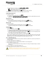
d) The LCD mimic will show the load connected to the input
LINE
via the
internal bypass.
e) The batteries are shown still connected to the input
LINE
and charging
(if the charger is still operative).
f)
The audible alarm will sound but can be silenced by pressing the
ON
button.
g) All metered parameters can be monitored as per normal.
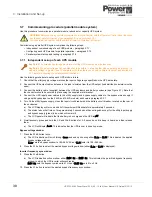
Note:
If the UPS input mains supply is disconnected when it is operating on
bypass, the UPS will not revert to battery power but will instead shut down with a
faIL
status indication. The UPS internal electronics will remain powered from
the battery and all leds will extinguish apart from the red
FAULT
led, which will be
permanently lit, and the audible alarm will sound continuously.
4.4.2 Transferring the load from the static bypass back to the UPS inverter
1. Press the
ON
button for approximately 3~5 seconds, until you hear a double
beep, then release it.
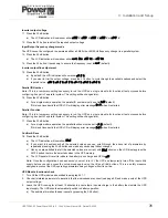
a) The LCD mimic will show the load connected to the UPS.
b) The audible alarm will sound but can be silenced by pressing the
ON
button.
c) The LCD display will revert to normal (on-line mode) indications.
LINE
UPS
LOAD
V
1
2
EC
O
N+
1
LINE
UPS
LOAD
1
2
EC
O
N+
1
LINE
UPS
LOAD
V
1
2
EC
O
N+1
LINE
UPS
LOAD
V
1
2
EC
O
N+
1


