background image

2:  General Description

16

UPS725-02-02 PowerWave 1000 (4.5 - 10 kVA) User Manual UK  Dated 13/03/15

2.7

Warranty

The PowerWave 1000 UPS is supplied with a limited warranty that the UPS and its component parts are free from defects
in materials and workmanship for a period of one year from the date of commissioning, or fifteen months from the date of
original delivery, whichever is the sooner. 

This warranty is the only warranty given and no other warranty, express or implied, is provided.

This warranty is invalidated if the UPS is used without having been commissioned by a fully trained and authorised
engineer. 

The warranty does not apply to any losses or damages caused by misuse, abuse, negligence, neglect, unauthorised
repair or modification, incorrect installation, inappropriate operating environment, accident, act of God, or inappropriate
application.

If the UPS fails to conform to the above within the warranty period then Uninterruptible Power Supplies Ltd will, at its sole
option, repair or replace the UPS. All replaced parts will remain the property of Uninterruptible Power Supplies Ltd.

As a general policy, Uninterruptible Power Supplies Ltd does not recommend the use of its products in:

• life support applications where failure or malfunction of the product can be reasonably expected to cause failure of

the life support device, or to significantly affect it’s safety or effectiveness.

• applications concerned with direct patient care.

Uninterruptible Power Supplies Ltd will not knowingly sell its products for use in such applications unless it receives in
writing assurances satisfactory to Uninterruptible Power Supplies Ltd that:

• the risks of injury or damage have been minimized.
• the customer assumes all such risks.
• the liability of Uninterruptible Power Supplies Ltd is adequately protected under the circumstances.

2.7.1  Extended warranty

The standard warranty may be enhanced by protecting the UPS with an extended warranty agreement (maintenance
contract). An extended warranty agreement enhances the standard warranty by providing the following:

• regular preventative maintenance inspections.
• guaranteed speed of response to operational problems.
• 24 hour telephone support.
• fully comprehensive cover (excluding batteries and capacitors).

Contact the Service Support Hotline on 0800 731 3269 for further details.

2.7.2  Additional service/maintenance support

In addition to providing support for the PowerWave 1000 UPS, Uninterruptible Power Supplies Ltd can provide
maintenance and support on a wide range of different UPS products. 

If you are interested in an extended warranty for your PowerWave 1000 UPS, or for any other UPS products you may
have, please complete the enquiry form shown below and return or FAX it to:

CAUTION: The UPS contains batteries that must be re-charged for a minimum of 12 hours every three months
to prevent deep-discharging. Batteries that have been deep-discharged, for whatever reason, are not covered
by this warranty.

Uninterruptible Power Supplies Ltd.
Woodgate
Bartley Wood Business Park
Hook
Hampshire
RG27 9XA

Tel: 01256 386700
0800 731 3269 (24 Hr.)
Fax: 01256 386701
Email: [email protected]

Summary of Contents for PowerWAVE 1000

Page 1: ...PowerWAVE 1000 4 5kVAto10kVASinglePhaseModels UserManual ...

Page 2: ......

Page 3: ...nual UK Dated 13 03 15 Document Control ISSUE DATE REVISION SUMMARY 725 02 00 05 08 14 Manual revised and issued as 725 02 00 725 02 01 03 11 14 Updated rack mounting procedure 725 02 02 13 03 15 Updated front cover to show Single Phase Output UPS ...

Page 4: ... easy to understand manual and will therefore assume no responsibility nor liability for direct indirect or accidental personal or material damage due to any mis interpretation of or accidental mistakes in this manual 2015 Uninterruptible Power Supplies Ltd This manual may not be copied nor reproduced without written permission of Uninterruptible Power Supplies Ltd ...

Page 5: ...ure rear panel 15 2 7 Warranty 16 2 7 1 Extended warranty 16 2 7 2 Additional service maintenance support 16 2 8 Extended Service enquiry form 17 3 Installation and Set up 3 1 Unpacking the UPS equipment 18 3 2 Selecting a suitable installation location 18 3 2 1 Clearances 19 3 3 Tower hardware configuration set up 20 3 4 Rack configuration set up 22 3 4 1 Installing the adjustable mounting rails ...

Page 6: ...tatic bypass back to the UPS inverter 43 5 Parallel UPS System Operating Procedures 5 1 System start up procedure 44 5 2 Shutdown procedure 46 5 3 Manual load transfer between inverter and bypass 46 5 3 1 Transferring the load from the UPS inverter to the internal bypass 46 5 3 2 Transferring the load from the static bypass back to the UPS inverter 47 6 Maintenance 6 1 Battery replacement 48 7 Tro...

Page 7: ...must be installed by a suitably qualified engineer who is aware of the potential shock hazards WARNING Before it is put into service this UPS must be set up and commissioned by a suitably qualified engineer in accordance with the procedures contained in Chapter 3 WARNING This UPS does not contain any user serviceable parts If the UPS develops a fault it must be repaired by a trained engineer You r...

Page 8: ...ween 0 40 C with relative humidity of 30 90 non condensing Before installing the equipment you must check to ensure that the UPS input voltage stated on the UPS data plate on the back of the unit matches your local utility supply voltage The UPS warranty will be rendered void and the manufacturer reserves the right to refuse replacement or compensation in the following events Accidental damage to ...

Page 9: ...LOW 1 2 EC O N 1 UPS Enclosure Battery Enclosure UPS Module or Single Module System ON OFF Enter Func tion LINE UPS LOAD V A Hz C LOW 1 2 EC O N 1 UPS Module 1 ON OFF Enter Func tion LINE UPS LOAD V A Hz C LOW 1 2 EC O N 1 UPS Module 2 ON OFF Enter Func tion LINE UPS LOAD V A Hz C LOW 1 2 EC O N 1 UPS Module 3 ON OFF Enter Func tion LINE UPS LOAD V A Hz C LOW 1 2 EC O N 1 UPS Module 4 Multi Module...

Page 10: ... batteries reduces the need for after sales service True on line technology continuously supplies your critical applications with stable regulated transient free pure sine wave AC power Highly efficient PWM sine wave technology yields excellent UPS efficiency The high crest factor of the inverter means that it can handle loads with peak inrush current characteristics and so avoids a need to upgrad...

Page 11: ... mounting it is usual to fit the UPS system near the bottom of a rack with the UPS enclosure mounted immediately above the battery enclosure see chapter 3 Installation for mechanical configuration details Optional equipment designed to enhance the overall UPS installation include a matching extended battery enclosure an external maintenance bypass enclosure and an isolation transformer The PowerWa...

Page 12: ...r the inverter Under these circumstances the inverter input power is provided by the battery via the DC DC boost converter which now turns on to increase the battery voltage to the level that required by the inverter to continue its normal operation The DC DC converter provides a regulated DC output as the battery voltage decays during battery discharge and includes voltage and current monitoring ...

Page 13: ...necting to the load The static switch connects the inverter output to the UPS output load terminals UPS OFF This is the state of the UPS when it is turned off from the operator control panel it is effectively running in bypass mode It also applies if the UPS locks out due to a fault If the utility supply is still available the battery charger will be live and maintain the battery charging UPS outp...

Page 14: ...e PowerWave 1000 is used as an off line UPS it is normally operated in its ON BYPASS mode Figure 2 2 with the load supplied via the static bypass line However the AC DC converter and battery charger are still powered up and maintain battery charging and the inverter section is turned on and operating on standby In the event of a static bypass supply error the inverter is immediately brought on lin...

Page 15: ...esent a low initial power demand which increases over time as the application grows and it is essential that the installed system can be expanded to meet the growing needs without compromising the existing load This situation is easily managed in a PowerWave 1000 parallel system installation which allows an additional module to be connected to an existing parallel system up to a maximum of four mo...

Page 16: ...to do this safely each module should by connected to the utility mains through a dedicated input supply circuit breaker and each UPS output should be similarly connected to the load via a dedicated output circuit breaker as illustrated in Figure 2 3 Once a module s output circuit breaker is open there is no load power being drawn from its inverter and it can be shut down in the normal way without ...

Page 17: ...ully illuminated when the number of on line UPS modules exceeds the number required to power the existing load by at least one module i e the system can afford to lose one module without having to transfer the load to the bypass supply due to an overload The led brightness will dim if the load increases or the number of on line modules decreases to the point where system redundancy no longer exist...

Page 18: ...This button is used to turn ON the UPS silence the audible alarm and activate certain other functions when used in conjunction with other buttons as described later in this chapter To turn ON the UPS the button must be held down for approximately five seconds until two audible beeps are heard OFF Button To turn OFF the UPS this button must be held down for approximately five seconds until two audi...

Page 19: ...s the battery being charged from the utility LINE and the LOAD connected to the UPS output and therefore being supplied with processed backed up power ON BATTERY MODE This mimic is displayed if the utility supply fails It shows the battery now providing the UPS and LOAD power The battery will sustain the UPS output until it is discharged whereupon the UPS will shutdown LOAD ON BYPASS MODE This mim...

Page 20: ...kVA 1 RS232 Port 6 Communication options slot SNMOP etc 2 Parallel termination resistor selection 7 Input supply circuit breaker 3 Parallel control CAN bus RJ45 ports 8 Bypass supply circuit breaker 10 kVA only 4 Emergency Power Off terminal block 9 Input Output power connection socket TB 5 Cooling fans 10 Battery connection socket 4 6 8 10 1 2 3 4 5 7 9 9 6 6 0 kVA Models 10 kVA Models EPO BREAKE...

Page 21: ...d slot Figure 2 7 item 6 Four optional interface cards are available to meet various communication needs DCE dry contact relay card R2E USE and SNMP Web These cards can be fitted into the options slot located behind a blanking plate on the UPS back panel as shown Full installation and set up procedures are provided in chapter 8 The software bundled with the UPS is compatible with most operating sy...

Page 22: ...pplies Ltd will not knowingly sell its products for use in such applications unless it receives in writing assurances satisfactory to Uninterruptible Power Supplies Ltd that the risks of injury or damage have been minimized the customer assumes all such risks the liability of Uninterruptible Power Supplies Ltd is adequately protected under the circumstances 2 7 1 Extended warranty The standard war...

Page 23: ... E mail us on service upspower co uk www upspower co uk Uninterruptible Power Supplies Ltd Woodgate Bartley Wood Business Park Hook Hampshire RG27 9XA Tel 01256 386700 Name Job Title Company Address Post Code Tel Fax E mail Please contact me to discuss Extended Warranty options for my PowerWave 1000 UPS Extended warranty options for my UPS System as below Manufacturer Model Nº Rating kVA Replaceme...

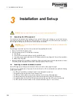
Page 24: ... of the UPS matches the equipment order details Contact your dealer if this is incorrect 3 2 Selecting a suitable installation location As the UPS weighs several kilograms the intended location must e able to safely support its weight To ensure correct operation and a long service life the site where the UPS is to be installed must satisfy the following environmental condition The UPS must be inst...

Page 25: ...nt them from tilting backwards Minimum 500 mm 1000 mm 300 mm 300 mm front back ventilation for cooling 300 mm 300 mm Rear cabling access Safe pedestrian passage 4 5 kVA 6 kVA 220 x 680 mm 8 kVA 10 kVA 264 x 680 mm UPS Enclosure tower footprint Tower mounting With regards to a Tower installation there are two sets of clearance criteria to consider the first is to satisfy the ventilation requirement...

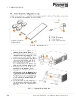
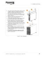
Page 26: ...t to the enclosure s left hand base as shown in Figure 3 3 top diagram 3 Attach two tower feet sole plates without feet to the enclosure s right hand base so that they do not protrude from the side of the enclosure as shown in Figure 3 3 top diagram This is necessary to ensure the UPS enclosure stands level when it is turned back onto its feet 4 Repeat steps 1 to 3 on the base of the battery enclo...

Page 27: ...3 between the enclosures using screws S1 to secure them together Figure 3 4 bottom diagram 10 Attach the angle brackets A2 to the top front of the UPS enclosure using two screws such that the lip of the bracket faces the front of the enclosure Figure 3 4 top diagram 11 Locate the new UPS enclosure top panel A3 into the bracket A2 and secure it in place by screwing it to the top rear of the enclosu...

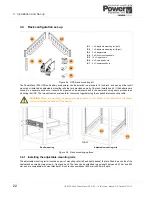
Page 28: ...le Figure 3 6 Rack mounting options 3 4 1 Installing the adjustable mounting rails The adjustable mounting rail kit contains a pair of mounting rails left and right handed that are fitted to each side of the cabinet and secured by two screws front and back The rails can be extended to any length between 543 mm and 925 mm and are compatible with most standard 19 inch rack assemblies of 600 mm to 90...

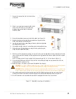
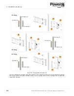
Page 29: ...r fixing points that will align with the equipment mounting handles and clip four captive nuts to the required fixing points Note The fixing points will vary according to the equipment height 2U 3U 4U as shown in Figure 3 8 9 Secure the adjustable mounting rail to the rack s front vertical fixing rail using two countersunk bolts B7 and adapter plate B3 see Figure 3 8 10 Repeat the steps 1 to 9 abo...

Page 30: ...anel so that it is correctly orientated To achieve this carefully pull the control panel forward to unclip it from its mounting rotate it to the correct angle then relocate it and press it back into place B5 B3 B7 B6 B3 B7 B6 B6 B3 B7 B5 B5 2U Fixing Adjustable rail Rack fixing rail Adapter plate Adjustable rail Rack fixing rail Adapter plate 3U Fixing Adjustable rail Rack fixing rail Adapter plat...

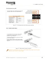
Page 31: ...n angle of 90º 3 5 1 Power cables Depending on the model variant the UPS input and output power cables can be connected either by means of a plug socket connector or hard wired to a terminal block If a plug socket arrangement is used then a ready cabled plug will be supplied with the UPS equipment If a terminal block connection is used then the provision of all external cables and fuses or circuit...

Page 32: ... Nm 19A 6 mm 6 0 kVA 33A 10 mm 2 Nm 25A 6 mm Ground Ground All cables must be supplied by the customer To connect the power Open the terminal block on the back of the UPS Connect the individual input output power cables and secure them in place using the two clamps fitted to the inside of the terminal block cover Output Line L21 Output Neutral N22 O P Earth Ground G2 Input Line L12 Input Neutral N...

Page 33: ...P Earth Ground G1 The 10 0 kVA UPS model is available as a three phase input single phase output version and connected as shown Input Neutral N1 10 kVA 3 Phase input UPS Input lines max current 54 3 A Input lines conductor 16 mm or 25 mm Input Neutral 16 mm or 25 mm Output max current 54 3A Output conductor 16 mm or 25 mm Battery max current 41A Battery conductor 10 mm In a parallel module system ...

Page 34: ...ich will remain lit c The LCD panel will indicate that the battery is on charge and the UPS is off 6 Simultaneously press and hold the ON and DOWN buttons for 3 5 seconds until a beep is heard and then release them a The LCD will display b_on This indicates that the UPS is now in its set up mode Bypass voltage window 7 Press the DOWN button twice a The LCD indication will scroll through tnon and e...

Page 35: ...above list of parameters by repeatedly pressing the DOWN button and make any necessary further changes c Once you are satisfied that all the selected values are correct with SAuE shown on the LCD display press the ENTER button to store the selected values in the UPS memory d The LCD panel will revert to indicate the battery is on charge and UPS is off Note Once the configuration has been saved you...

Page 36: ...en extinguish except for the utility input supply and bypass supply green leds which will remain lit c The LCD panel will indicate that the battery is on charge and the UPS is off 6 Simultaneously press and hold the ON and DOWN buttons for 3 5 seconds until a beep is heard and then release them a The LCD will display b_on This indicates that the UPS is now in its set up mode Bypass voltage window ...

Page 37: ... functional test purposes before configuring it as part of a parallel system This setting will be changed later 17 Press the DOWN button a For a single module operation the parallel function must be set to P 0l default If this is set incorrectly the UPS LCD will display error message Er21 when it is started Confirm Save 18 Press the DOWN button a The LCD indication will now show SAuE b If you want...

Page 38: ...les with their intended identification number as an aide memoir Carry out the follow procedure on each module in turn beginning with module 1 Setting the terminal resistors 1 Ensure that the parallel bus cables are connected in a ring network between the parallel UPS modules 2 On the UPS modules at either end of the parallel system i e bottom most top most or left most right most turn ON switch S1...

Page 39: ...n using the ON and DOWN buttons This is a safety measure designed to prevent the UPS operating parameters being changed while it is on line Repeat the above procedure on ALL modules 3 7 4 Parallel system testing Parallel communications test 1 Turn on the utility input supply to all the modules except module 1 the module set as ld01 and check that the module indications are as shown in the top row ...

Page 40: ...graph 2 5 1 Note If you are using the application on a laptop that does not have a serial port you will require a readily available USB to RS232 serial adapter cable Er16 Output parameters setting error Cause One or more parameter settings conflict between each module Solution Check the parameter settings are identical in each module as per paragraph 3 7 1 Er17 Conflicting ID Number Cause parallel...

Page 41: ...n memory a Click the Yes button in the Writing confirmation dialog b The UPS will beep twice to confirm that it has received the data c Click OK to clear the Transmit OK dialog 3 To save the machine profile data to the UPS memory you must reset the UPS by turning OFF its input supply then turning it back ON again 4 At any time when the UPS is re started you can download the data held in the UPS me...

Page 42: ...g 3 To apply the changes you must now turn OFF the UPS input supply then turn it back ON again 3 8 4 Output voltage calibration This procedure can be used to calibrate the UPS output voltage and requires access to the UPS output terminals to enable the output voltage to be measured It can be used to accurately trim the output voltage in a single module installation or to match the output of all th...

Page 43: ...a file 1 As described above to add the current configuration to the UPS data file select Record Add New on the UPS Setting Tool menu bar a The new record will be added to the bottom of the data file Updating an existing UPS data file record To update an existing data file record with configuration data displayed in the UPS Setting Tool 1 Open the UPS data file 2 Select the particular record that y...

Page 44: ...test for about 4 seconds to check the battery operation a If the UPS does not complete its self test successfully the LCD will show a FAIL status and the FAULT led will illuminate b If the self test is successful the LCD will show an OK status for about 5 seconds then change over to display the normal on line indications c The utility input and bypass input power leds green remain illuminated 4 Yo...

Page 45: ...seconds c When control system boot up has completed all the leds will turn off the LCD mimic will display the UPS connected to the battery and the UPS status will be shown as off Following the second button press a The LCD display will initially keep the UPS off screen displayed for a few seconds and will then run a self test routine for several seconds during which time the LCD screen will show t...

Page 46: ...unction can display the input voltage input frequency load voltage load frequency percentage load battery voltage and internal temperature When the UPS is operating you can scroll through these parameters using the DOWN or UP button Note that the three arrowheads on the LCD mimic diagram identify the source of the meter indication as being either Input Load or Battery LINE UPS LOAD V LINE UPS LOAD...

Page 47: ...on to activate the selected status and return to the normal LCD Display Note If you do not press the FUNCTION button the LCD will revert to its normal display automatically after approximately 10 seconds and the selected audible alarm setting will be activated 4 2 3 Battery test You can carry out a periodic battery test using the following procedure This test effectively places the UPS in its On B...

Page 48: ...for a few seconds before the unit completely shuts down b The UPS output will turn OFF and the load will no longer be supplied 4 3 2 UPS shutdown when on battery This procedure describe the shutdown sequence when turning OFF the UPS when it is operating in its standby On Battery mode You would typically use this procedure during a prolonged utility mains failure if you chose to shutdown the critic...

Page 49: ...o the UPS internal inverter bypass transfer operation 4 4 1 Transferring the load from the UPS inverter to the internal bypass 1 Press the OFF button for approximately 3 5 seconds until you hear a double beep then release it d The LCD mimic will show the load connected to the input LINE via the internal bypass e The batteries are shown still connected to the input LINE and charging if the charger ...

Page 50: ...ted on the rear of the enclosures a The UPS fans will start b The control system will boot up and initially turn on all the leds and LCD symbols for a few seconds c Once the control system has booted the ECO and N 1 leds will extinguish d The UPS will then carry out some internal self tests e When the self tests are completed the LCD screen will display an Er21 error code 5 ON MODULE 1 Turn ON the...

Page 51: ... led will illuminate If the self test is successful the LCD will show an OK status for about 5 seconds 10 When the ON button has been pressed on all module and they have successfully passed their battery checks they will carry out some further parallel operation checks and once these final tests are passed typically 5 10 seconds the modules will then simultaneously transfer their output from the s...

Page 52: ...it connected in parallel with the UPS to provide an alternative power source for the load supply Such installations are designed to enable the UPS system to be totally powered down without disrupting the load for example for troubleshooting or repair To prevent the external bypass from back feeding the UPS inverter and causing it damage the transfer between the UPS and external bypass is only perm...

Page 53: ...L status indication The UPS internal electronics will remain powered from the battery and all leds will extinguish apart from the red FAULT led which will be permanently lit and the audible alarm will sound continuously 5 3 2 Transferring the load from the static bypass back to the UPS inverter To transfer the load from the internal static bypass supply On bypass mode to normal operation On line m...

Page 54: ...d end of the UPS front panel This will expose two front panel securing screws 2 Remove the two front panel securing screws using a Phillips screwdriver 3 Carefully pull the fascia away from the front panel to expose the battery packs 4 Cut any cable ties that are holding the battery cables in place 5 Disconnect the battery connector s and carefully withdraw the battery pack s Use the above procedu...

Page 55: ...a single module installation if the UPS shuts down due to a fault condition and is able to transfer the load to the static bypass then it will do so to maintain the load supply lower illustration 7 2 Error codes In general under fault conditions the red FAULT led will illuminate and an audible warning will be given Many faults can be identified by briefly pressing the OFF button which then display...

Page 56: ...onnectors to determine that they are undamaged and the insulation is sound Replace the output cables if necessary 3 Contact your local dealer right away if you can find no problem with the above Er11 UPS Over temperature 1 Remove any objects obstructing the ventilation louvers 2 Check to ensure that the cooling fans are working properly see also Er14 and contact your local dealer to replace the fa...

Page 57: ... short circuit when the output supply via the bypass line If the output load is short circuited in bypass mode a The utility fuse breaker will be activated open circuited to prevent the output load from damage b You must replace the fuse with a fuse of the same rating after the cause of the short circuit condition has been rectified Symptom Possible Solution UPS fails to provide battery back up or...

Page 58: ... is abnormal a The audible alarm will beep continuously b The FAULT led will illuminate c The UPS will cut off the load supply 7 5 4 Inverter over current and output voltage out of tolerance If the UPS develops a fault and its inverter delivers an over current and out of tolerance voltage a The UPS will transfer the load to the bypass line as long as the utility supply is normal b The UTILITY led ...

Page 59: ...ly long utility supply outage In the case of an abnormal utility supply suitable UPS management software will also enable a system administrator to monitor all concerned networks from a central point and identify bottlenecks at an early stage In spite of extensive system monitoring if an administrator fails to intervene in a timely manner serious damage can still occur It is important therefore th...

Page 60: ...ion and control system If UPSMAN detects voltage variations or a power failure it can execute various system event routines by means of which for example the server is switched off or a warning is sent to the connected users These system event routines are a part of the management software and can be configured in accordance with local application requirements The software of your PowerWave 1000 U...

Page 61: ...on the WAVEMON installation CD RCCMD RCCMD Remote Console Command Module for multi server shutdown is an independent software module intended for transmitting and receiving remote commands The new version RCCMD2 is similar to WAVEMON available for the most widespread operating systems Using the RCCMD send function the SNMP adapter can send status messages to connected users or initiate automatic s...

Page 62: ...UPS to facilitate an alternative USB interface The USB configuration detail is described in paragraph 2 5 8 6 R2E second RS 232 card This card can be installed in the Option Slot located on the rear of the UPS to facilitate an alternative RS 232 interface The RS 232 configuration detail is described in paragraph 2 5 Figure 8 4 USB Option card Figure 8 5 RS232 Option card ...

Page 63: ...stment 0 1 2 3 selected by software Voltage regulation 2 Capacity 4500VA 4050W 6000VA 5400W 8000VA 7200W 10000VA 9000W Power factor 0 9 Lagging Wave form Sine wave THD 3 linear load Frequency stability 0 2 unless synchronised to line Synchronisation window 1 Hz 3Hz selectable via software Transfer time Inverter Bypass typical 0 ms Crest factor 3 1 DC Start Yes Efficiency Efficiency AC to AC Normal...

Page 64: ...splay Panel Status on LED and LCD On line mode On battery mode ECO mode Input supply Bypass supply Battery low Battery bad disconnect Overload Transfer with interruption UPS fault LCD Metering display Input voltage Input frequency Output voltage Output frequency Load percentage Battery voltage Internal temperature LCD Status display Module mimic showing operating status fault and diagnostic indica...

Page 65: ... approx 450W 500W 600W 700 Mechanical Data Dimensions WxHxD mm 440x88x680 440x132x680 19 rack mounting space 2U 3U x680 3U 3U x680 Weight net 24 kg 26 kg Input output power connections Hard wired to terminal block Other connectors 1 x USB 1 x RS232 1 x 2 pole EPO Connector 1 x Interface Slot Standards Safety EN 62040 1 1 IEC 60950 1 EMV Compatibility EN 62040 2 EN 61000 3 2 EN61000 3 3 FCC A Perfo...

Reviews: