


3: Installation and Set-up
20
UPS725-02-02 PowerWave 1000 (4.5 - 10 kVA) User Manual UK Dated 13/03/15
3.3
Tower hardware configuration set-up
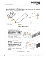
Using the components shown in Figure 3.2, which are supplied as standard for both the UPS and battery enclosures, the
UPS can be configured as a floor-standing Tower unit, as follows:
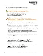
Figure 3.2 Tower configuration kit
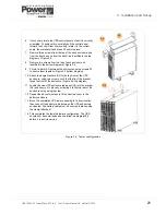
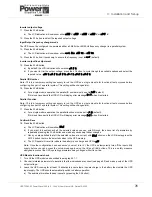
Figure 3.3 Attaching the enclosures’ feet
A2
A1
A3
A4
All necessary screws and
hardware included.
A1
4 x Tower feet
A2
1 x Tower top panel bracket
A3
1 x Tower top panel
A4
1 x Tower / battery cabinet tie bar
A1
Sole plate
Foot
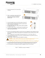
1. First, assemble two tower feet (A1) by attaching
the foot to the sole plate (see Figure 3.2).
2. Turn the UPS enclosure on its side and attach the
two assembled tower feet to the enclosure’s left
hand base, as shown in Figure 3.3 top diagram.
3. Attach two tower feet sole plates (without feet) to
the enclosure’s right hand base so that they do
not protrude from the side of the enclosure as
shown in Figure 3.3 top diagram.
This is necessary to ensure the UPS enclosure
stands level when it is turned back onto its feet.
4. Repeat steps 1 to 3 on the base of the battery
enclosure; but in this case ensure that the
protruding feet are fitted to the battery enclosure’s
right hand side.
Note that Figure 3.3 lower diagram is provided to
illustrate the positional relationship between the
UPS and battery enclosure feet only. In practice,
the UPS enclosure would not normally be laying
on top of the battery enclosure while fitting the
battery enclosure feet.
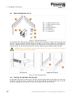
5. Carefully lift both assemblies and stand them on
their feet adjacent to each other with the battery
enclosure to the right of the UPS enclosure (see
Figure 3.4).
A1
A1