UPS725-02-02 PowerWave 1000 (4.5 - 10 kVA) User Manual UK Dated 13/03/15
11
2: General Description
2.4
Operator control panel
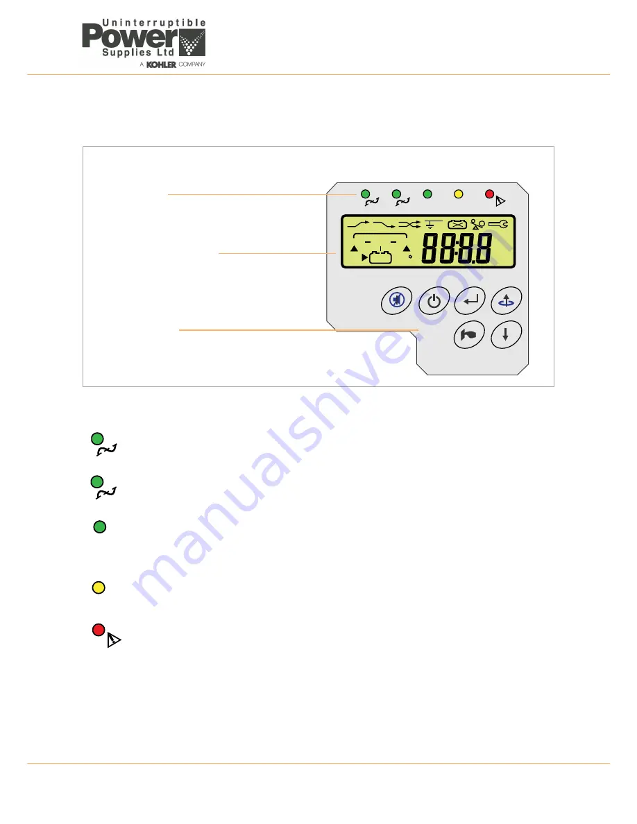
The UPS is fully controlled from the operator control panel located on the front of the unit.
Figure 2.4 Operator control panel
2.4.1 LED Indicators
Input mains supply status
This led indicates that the utility mains voltage applied to the UPS input terminals is within the specified operating range
(168~288 VAC) and is therefore normally illuminated. The led flashes if the supply falls to within 120~168 VAC and
extinguishes altogether in the event of a total utility supply failure.
Bypass mains supply status
This indicates the state of the bypass mains supply. This supply is internally linked to the UPS input supply terminals in
the 4.5 kVA, 6 kVA and 8 kVA models and this indicator will therefore reflect the utility supply status indication above;
however in the 10 kVA the UPS bypass terminals are optional connected to a dedicated bypass supply.
N+1 Redundancy status
Used in a parallel system only. This led is fully illuminated when the number of on-line UPS modules exceeds the number
required to power the existing load by at least one module – i.e. the system can afford to lose one module without having
to transfer the load to the bypass supply due to an overload.
The led brightness will dim if the load increases (or the number of on-line modules decreases) to the point where system
redundancy no longer exists.
ECO Mode
This led illuminates when the UPS is set to operate in the ECO mode, which is available on a single module installation
only.
UPS fault indication
This LED illuminates to indicate a fault condition within the UPS that needs attention.
1
2
EC
O
N+
1
O
N
O
FF
En
te
r
Fu
nc
tio
n
LINE
UPS
LOAD
V
A
%
Hz
C
LOW
?
Led indicators
A row of leds indicate the UPS input and output
power status, together with a general fault
warning.
Alpha-numeric LCD Display
Provides indication of the UPS operating mode
together with the input, output, and battery supply
parameters. It also displays error messages and
UPS set-up data via a system of configuration
menus.
Operator Keypad
The keypad contains 6 keys that are used to
navigate through the UPS control menu system
and turn the UPS OFF/ON.
The user-friendly UPS control panel comprises three areas:
1
2
N+
1
EC
O


