2: General Description
10
UPS725-02-02 PowerWave 1000 (4.5 - 10 kVA) User Manual UK Dated 13/03/15
.
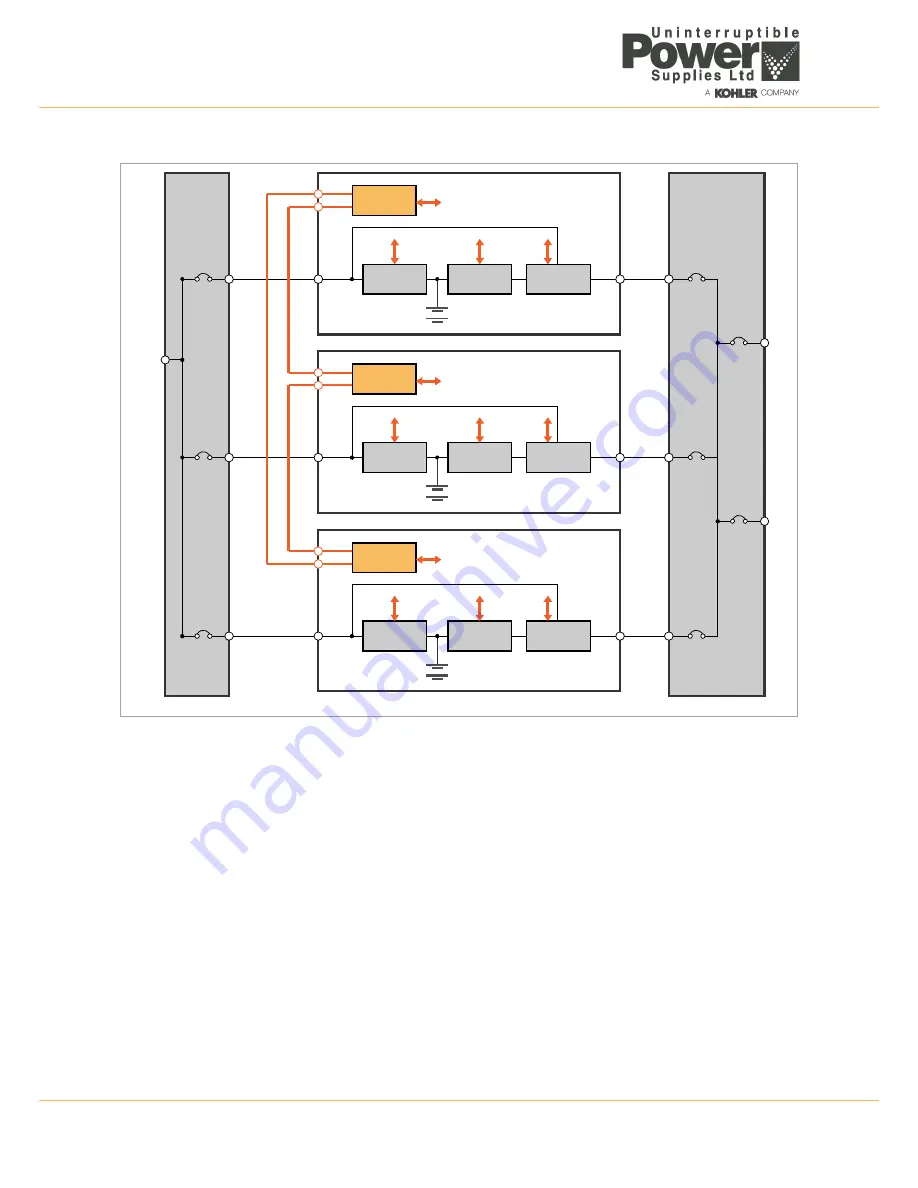
Figure 2.3 PowerWave 1000 UPS Parallel system
Inter-module frequency synchronisation and load sharing
Using sensing signals passed over the parallel control bus, each UPS is able to compare its own frequency and output
current with that of its neighbouring modules and carry out fine adjustments to achieve balanced conditions.
Isolating a module from the system
As explained immediately above, if a parallel system is operating with module redundancy it is possible to isolate a module
from the system for service or repair without affecting the remaining modules, or load. But in order to do this safely, each
module should by connected to the utility mains through a dedicated input supply circuit breaker and each UPS output
should be similarly connected to the load via a dedicated output circuit breaker – as illustrated in Figure 2.3.
Once a module’s output circuit breaker is open there is no load power being drawn from its inverter and it can be shut
down in the normal way without affecting the remain on-line modules.
BATTERY
Module 1
Output
Dustribution
Panel
CB1
Static Bypass Line
Load
Load
UPS1
O/P
UPS2
O/P
UPS3
O/P
Pa
ra
ll
e
lc
on
tr
ol
bus
ca
bl
e
s
AC/DC
CONVERTER
PARALLEL
LOGIC
DC/AC
INVERTER
STATIC
SWITCH
CB
BATTERY
Module 2
CB2
Static Bypass Line
AC/DC
CONVERTER
PARALLEL
LOGIC
DC/AC
INVERTER
STATIC
SWITCH
BATTERY
Module 3
CB3
Static Bypass Line
AC/DC
CONVERTER
PARALLEL
LOGIC
DC/AC
INVERTER
STATIC
SWITCH
CB
Input
Supply
Panel
CB1
Utility
Mains
Supply
CB2
CB3


