SECTION 6
OPERATION
38
6
6.1
Overview
CAUTION
Do not turn off the power during pump operation. If the power is turned off repeatedly, the
touch-down bearing may need to be replaced. When the power is turned off during operation,
levitation is maintained using regenerative power. After decelerating to a lower speed, levitation
is stopped and the rotor is supported by the touch-down bearing.
Therefore, repeated touchdown shortens the life of the bearing.
6.1.1 Introduction : Operation Modes
When the POWER switch is turned on, the pump starts self-diagnosis.
When the result is normal, operation is enabled. When an abnormal condition is detected, the
STATUS lamp lights up in orange.
The pump can be started/stopped in a number of different ways ; using a switch, contact signal,
or communication.
However, the pump cannot be started/stopped using two or more of these ways at the same
time.
Determination of which start/stop instruction to be followed depends on the operation mode
selected.
There are five operation modes as listed below.
(1) LOCAL mode where switches on the control panel are used for control
(2) REMOTE mode where contact signals are used for control
(3) RS-232C mode where RS-232C communication is used for control
(4) RS-485 mode where RS-485 communication is used for control
The pump starts in the REMOTE mode described in (2) when the power is turned on including
when recovering from a power failure.
Switch to an operation mode prior to starting/stopping the operation.
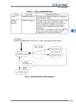
Transit between operation modes is shown in Fig. 6-1. The state of the POWER lamp is
different between the LOCAL and other modes, as shown in Table 6-1.
Hold down the RESET button to transit between the LOCAL and REMOTE modes.
To transit to a communication mode, send an online request via the corresponding
communication media.
Summary of Contents for UTM2300 Series
Page 2: ...This page is intentionally left blank...
Page 10: ...viii Location of Label...
Page 20: ...6 1 1 2 Descriptions This page is intentionally left blank...
Page 21: ...2 2IDENTIFICATION AND FUNCTION 2 1 Pump Main Unit 2 2 Control Panel 2 3 External I F Panel...
Page 30: ...16 3 3 3 Controller This page is intentionally left blank...
Page 36: ...22 4 4 3 Standards Fulfilled This page is intentionally left blank...
Page 50: ...36 5 5 5 Notes on Transportation This page is intentionally left blank...
Page 72: ...58 6 6 8 Communication Specifications This page is intentionally left blank...
Page 73: ...7 7GAS PURGE...
Page 82: ...68 8 8 6 Turbo Molecular Pump Return Request This page is intentionally left blank...
Page 95: ...10 10WARRANTY CLAUSES...
Page 98: ...84 10 This page is intentionally left blank...
Page 100: ...Index Index 2 This page is intentionally left blank...


