


2.2
Control Panel
9
2
2.2
Control Panel
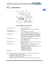
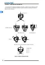
Fig.2-2
Outline View of Control Panel
(1) AC INPUT connector .......................Power cable receptacle.
(Refer to Section 5.2 "Connection of Power Cable".)
(2) POWER Switch................................Power switch.
(3) START/STOP button .......................Push to acceleration or deceleration.
During LOCAL MODE, control by maintained push.
(4) RESET button ..................................When occur ALARM or WARNING, after remedying the
cause of the ALARM, an abnormal state is released by
pushing button. By maintained push, REMOTE MODE
and LOCAL MODE are changed.
(5) POWER lamp...................................This lamp lights or blinks while power on. (green)
lights : REMOTE MODE
blinks : LOCAL MODE
(6) ROTATION lamp .............................Operation indicator lamp indicating that the pump's rotor
is running. (green)
(7) STATUS lamp .................................Operation indicator lamp indicating that the pump's
operation status. (green
・
orange) (Note 1)
green/lights : Rotational speed reaches 80 % rated value
green/blinks : Accelerating
orange/lights : ALARM occurs
orange/blinks : Warning occurs
(8) NET lamp .........................................This lamp is always turned off.
(Note 1) The pattern when both green and orange are lit and blink becomes the following.
・
When warning occurred during rating speed.
green/light and orange/blink : green - orange - green - orange - …
・
When warning occurred during acceleration.
green/blink and orange/blink : green - orange - turned off - green - orange - turned off -…
Summary of Contents for UTM2300 Series
Page 2: ...This page is intentionally left blank...
Page 10: ...viii Location of Label...
Page 20: ...6 1 1 2 Descriptions This page is intentionally left blank...
Page 21: ...2 2IDENTIFICATION AND FUNCTION 2 1 Pump Main Unit 2 2 Control Panel 2 3 External I F Panel...
Page 30: ...16 3 3 3 Controller This page is intentionally left blank...
Page 36: ...22 4 4 3 Standards Fulfilled This page is intentionally left blank...
Page 50: ...36 5 5 5 Notes on Transportation This page is intentionally left blank...
Page 72: ...58 6 6 8 Communication Specifications This page is intentionally left blank...
Page 73: ...7 7GAS PURGE...
Page 82: ...68 8 8 6 Turbo Molecular Pump Return Request This page is intentionally left blank...
Page 95: ...10 10WARRANTY CLAUSES...
Page 98: ...84 10 This page is intentionally left blank...
Page 100: ...Index Index 2 This page is intentionally left blank...


