TAPE OUT Function
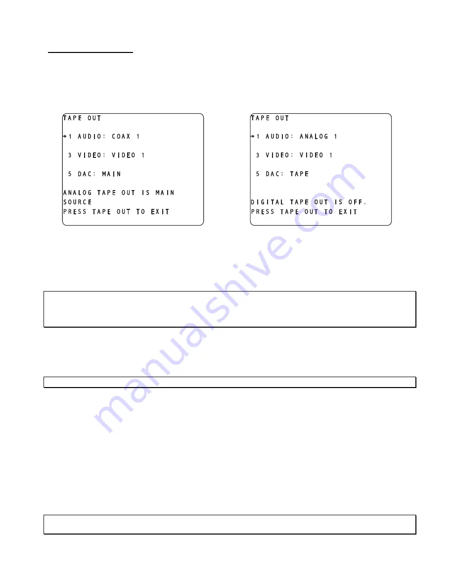
This feature simultaneously controls the routing of signals to the analog and digital audio, and video tape out
jacks.
Pressing the
TAPE OUT
button once displays the
TAPE OUT
menu, shown in figure 73 or 74, on the video
monitor display. The menu title “
TAPE OUT
” is displayed in the upper left. The
INPUT NAMES
shown in
this figure are for example only and will most likely differ from the users set up.
Figure 74 - Video Display of the TAPE
OUT Menu with Optional Tape Out DAC
installed and set to TAPE
Figure 73 - Video Display of the TAPE
OUT Menu with Optional Tape Out DAC
installed and set to MAIN
To route a signal to the appropriate
TAPE OUT
jack(s), press the
TAPE OUT
button and press button #
1
to
assign an audio source to the audio
TAPE OUT
jacks and button #
3
to assign a video input jack to the video
TAPE OUT
jacks.
Note
: The composite/multi format and s-video circuits are completely independent as far as video signals go.
This is to say that a composite video input signal can be output only through the composite video outputs, S-
video input signals can be output only through the s-video outputs and multi format input video signals can
only be output via the multi format video output.
This menu is completely dynamic. When the audio source is from an analog jack, the digital tape out jacks are
disabled. This is indicated in both the OSD and VFD. When a digital input jack is selected as the source, it is
routed to both the analog and digital tape out jacks. When the main DACs are selected (default), this is
indicated in both the VFD and OSD. If the optional tape out DAC is not installed, the option to select it (via
button #
5
) is not shown.
Note/Exception
: An RF input signal will be routed to the analog audio tape out jacks only.
The control circuitry to the video tape out jacks is common to both composite and s-video. Example: when the
user routes the composite video signal from a composite input # 1 jack to the composite video tape out jack,
the s-video # 1 input simultaneously gets routed to the s-video tape out jack. If composite video # 2 input jack
is routed to the composite video tape out jack, then s-video input # 2 jack gets routed to the s-video tape out
jack, and so on. There is no multi format video tape out jack so these input signals cannot be recorded.
Button #
5
allows the user to select whether the signal at the analog
TAPE OUT
jack will be derived from the
main output DACs or the optional tape out DAC (if installed), by displaying
MAIN
or
TAPE
on the display. If
the optional tape out DAC has not been installed, there will be no option to edit above button # 5. This setting
is only relevant if the analog tape out source is set to a digital input jack. All analog inputs are routed directly
to the
TAPE OUT
jacks, without A/D to D/A conversion.
Now the routing is completed, press
TAPE OUT
again to clear the video display. The
MASTER VOLUME
can
be controlled in this menu via the
LEVEL LEFT
/
RIGHT
buttons.
Please refer to page 45 for additional
TAPE
OUT
features and options information.
CAUTION
: It is not advisable to route a 5.1 source (DTS/AC-3) to the optional tape out DAC as this section
does not contain Dolby Digital or DTS decoding capabilities. Full scale noise will be output!
83
Summary of Contents for Casablanca III
Page 23: ...13 Setup Menus and Pages Figure 14 Setup Menus and Pages ...
Page 25: ...15 STEP BY STEP SETUP GUIDE ...
Page 34: ...24 Setup Flowcharts A P Flowchart A Setup Subwoofer s ...
Page 35: ...Flowchart B Front Left Right Configuration 25 ...
Page 36: ...Flowchart C Front Center Configuration 26 ...
Page 37: ...Flowchart D Left Right Surround Configuration 27 ...
Page 38: ...Flowchart E Surround Center Configuration 28 ...
Page 39: ...Flowchart F Sides Configuration 29 ...
Page 40: ...Flowchart G Setup Speaker Levels 30 ...
Page 41: ...Flowchart H Setup Speaker Delays 31 ...
Page 42: ...Flowchart I Setup Dolby Digital 32 ...
Page 43: ...Flowchart J Setup DTS 33 ...
Page 44: ...Flowchart K Setup Circle Surround 34 ...
Page 45: ...Flowchart L Copy Input Speaker Parameters 35 ...
Page 46: ...Flowchart M Setup Default Mode 36 ...
Page 47: ...Flowchart N Setup Post Process 37 ...
Page 48: ...Flowchart O Map Input Jacks 38 ...
Page 49: ...Flowchart P Setup Analog Input Levels 39 ...
Page 88: ...REMOTE CONTROL 78 ...
Page 114: ...APPENDIXES 104 ...


