


FRONT PANEL OPERATIONS
This section describes the functionality of each button on the Casablanca III’s front panel display only. For
remote functionality descriptions, please refer to the section entitled
REMOTE CONTROL OPERATIONS
later in this manual. Descriptions for front panel buttons/functionality not covered in this section can be
found in the preceding
FRONT PANEL LAYOUT
section.
Input Select Menus
When the Casablanca III is first powered up via the
MAIN POWER
switch on the back panel, it will check all
software and hardware and then it will be in the default standby mode as soon as the front panel
MAIN
POWER
LED is lit. Pressing the
MAIN
button on the front panel will result in the front panel display showing
the start-up routine and then the current
INPUT SELECT
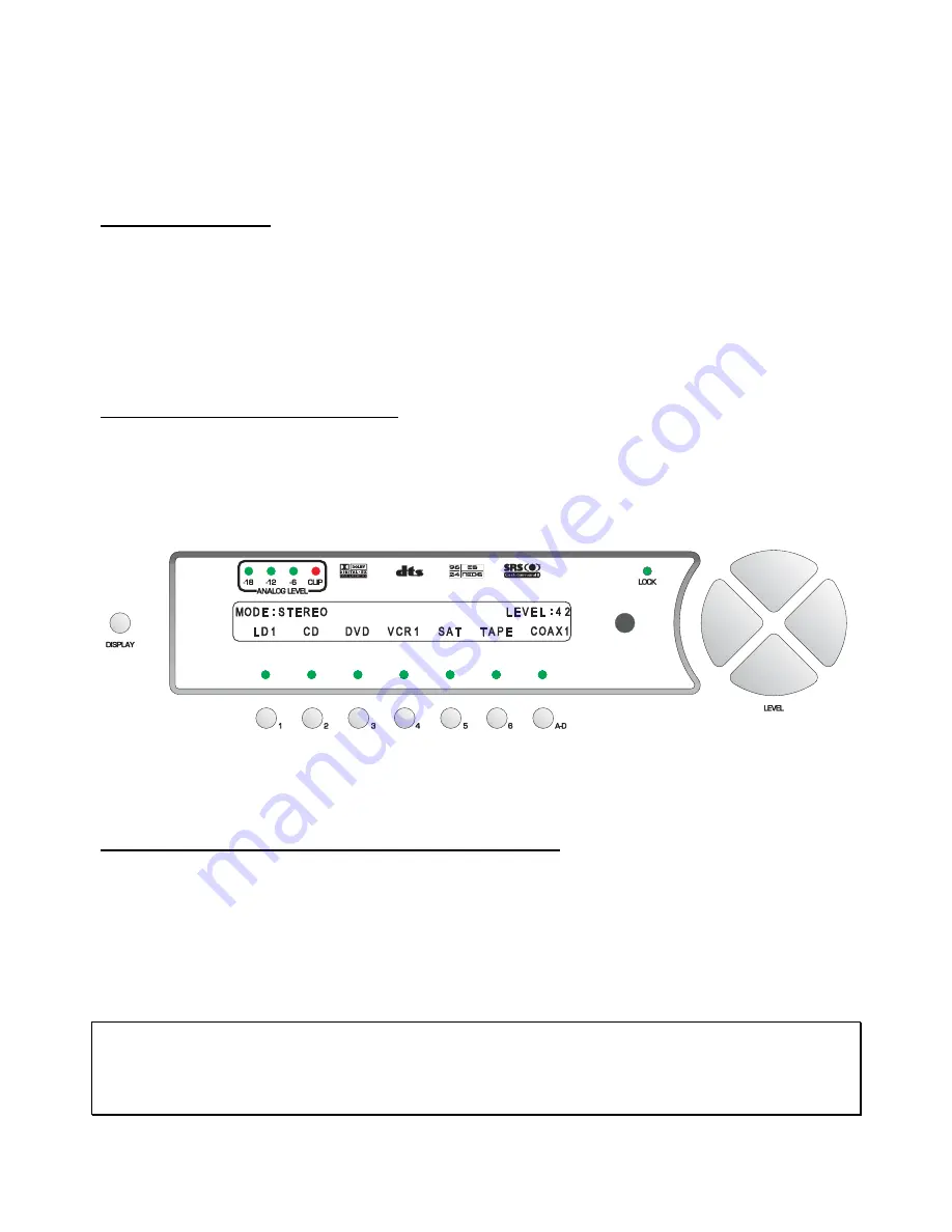
page, shown in figure 15 below. As this menu
appears, the
MAIN
LED turns off. This display will be on all of the time during normal operation and will
change only when one of the function buttons or the
STATUS
button is pressed.
When the Casablanca III is put into standby, the front panel display will say
CHECKING DISPLAY
and then
all pixels will be illuminated for approximately 10 seconds. This prolongs the life of the display.
Changing Inputs and Input Select Pages
The
INPUT NAMES
shown in this figure are for example only and will most likely differ from the user’s set
up. There are two
INPUT
SELECT
pages, giving the user a total of 12 inputs. Buttons
1
through
6
are used
to select a desired input, or audio/video source. The LED above the selected button will illuminate when
pressed. When the Casablanca III exits standby mode, the last active
INPUT
SELECT
will be selected.
Pressing the
LEVEL
LEFT
or
RIGHT
buttons toggles between the two
INPUT
SELECT
pages.
* * *
Figure 15 - Front Panel Display of the current INPUT SELECT page
Pressing the
LEVEL UP/DOWN
buttons will adjust the master volume for all speakers. A temporary bar
graph appears on the VFD and OSD as the master volume is being adjusted. This value ranges from
0
to
73
, relative maximum.
Selecting Mapped Input Jacks for the Currently Selected Input
Pressing the
A-D
button will toggle between the input jacks that are mapped to this
INPUT SELECT
button.
Please refer to page 41 (
Search Order
) for important, detailed information regarding using the
A-D
button.
* * *
The
MUTE
button will toggle the audio between the master volume level and
MUTE
level* in all speakers
each time it is pressed. When the mute feature is enabled, the word
LEVEL
in the VFD will be replaced with
the word
MUTED
, which will remain displayed until the mute is disabled. The
MUTE
feature is active in all
menus.
*
Note
: The factory default value for
MUTE
is
0
, which is to say that when the
MUTE
button is pressed, the
output level of all channels will be completely muted (master volume =
0
). The Casablanca III offers a
feature in the
SETUP
/
GLOBAL/MUTE-VOLUME
sub menu whereby when the
MUTE
button is pressed, the
Casablanca III will mute to a user defined master volume level. Please refer to page 70 for additional
information regarding this feature.
40
Summary of Contents for Casablanca III
Page 23: ...13 Setup Menus and Pages Figure 14 Setup Menus and Pages ...
Page 25: ...15 STEP BY STEP SETUP GUIDE ...
Page 34: ...24 Setup Flowcharts A P Flowchart A Setup Subwoofer s ...
Page 35: ...Flowchart B Front Left Right Configuration 25 ...
Page 36: ...Flowchart C Front Center Configuration 26 ...
Page 37: ...Flowchart D Left Right Surround Configuration 27 ...
Page 38: ...Flowchart E Surround Center Configuration 28 ...
Page 39: ...Flowchart F Sides Configuration 29 ...
Page 40: ...Flowchart G Setup Speaker Levels 30 ...
Page 41: ...Flowchart H Setup Speaker Delays 31 ...
Page 42: ...Flowchart I Setup Dolby Digital 32 ...
Page 43: ...Flowchart J Setup DTS 33 ...
Page 44: ...Flowchart K Setup Circle Surround 34 ...
Page 45: ...Flowchart L Copy Input Speaker Parameters 35 ...
Page 46: ...Flowchart M Setup Default Mode 36 ...
Page 47: ...Flowchart N Setup Post Process 37 ...
Page 48: ...Flowchart O Map Input Jacks 38 ...
Page 49: ...Flowchart P Setup Analog Input Levels 39 ...
Page 88: ...REMOTE CONTROL 78 ...
Page 114: ...APPENDIXES 104 ...


