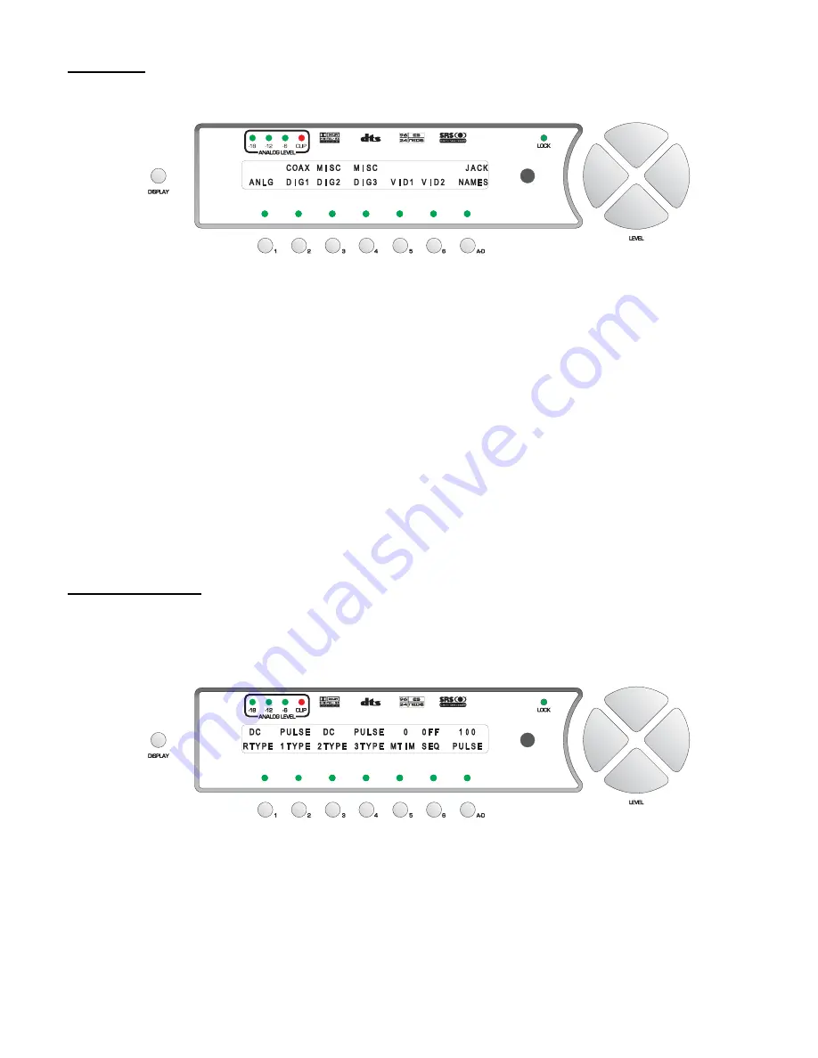
Jack Names
From the first
GLOBAL
page, button #
2
accesses a series of sub menus, which allow the user to name all of the
Casablanca III’s input jacks, both audio and video. The
JACK NAMES
sub menu is shown in figure 54.
Figure 54 - Front Panel Display of the SETUP
/
GLOBAL
/
JACK NAMES Sub Menu
Pressing button #
1
accesses a sub menu that allows the analog audio input jacks to be named. Button #
2
does the
same for the coaxial digital audio input jacks, whereas buttons #
3
and
4
allow the user to name all non-coaxial digital
audio input jacks. Buttons #
5
and
6
lead to sub menus that allow the naming of the video jacks. The composite, S
and multi format video jacks are internally tied together when it comes to mapping them, and subsequently switching
and naming them. In other words, where
COMPOSITE 1
video jack is mapped, so are the
S-VIDEO 1
and
Multi
Format 1
jack, where
COMPOSITE 2
video jack is mapped, so are the
S-VIDEO 2
and
Multi Format 2
input jacks,
and so on. Since the
COMPOSITE 1
input jack cannot be mapped differently than the
S-VIDEO 1
or
Multi Format 1
input jacks, they also share the same jack name.
Example of editing a jack name:
To edit the name of analog input jack 1, press button #
1
from the menu shown above. This displays the
NAME
ANALOG
sub menu. Then press button #
1
(first analog input jack name). Press the
LEVEL
UP
/
DOWN
buttons to
select the desired VFD character and the
LEVEL LEFT
/
RIGHT
to change character positions. Once selected,
pressing the
DISPLAY
button once will clear the current jack name. The character to be edited will blink or have a
cursor below it. The VFD name for all audio input jacks can be up to 6 characters and the video jack names up to 5.
Press the
A-D
button to edit the OSD name.
OSD
will be displayed above the
A-D
button in the VFD. ALL OSD
names can be up to 15 characters and the current character to be edited will blink.
Remote Power Jacks
The
REMOTE POWER
jack and three
MAIN POWER
jacks on the rear panel can be programmed to output 12V,
either straight
DC
or as a
PULSE
. This feature is used to automatically turn on other system components such as
power amplifiers, etc, when the Casablanca III is taken out of Standby. From the first
SETUP
/
GLOBAL
page, press
button #
3
to access the
REMPWR
sub menu shown in figure 55.
Figure 55 - Front Panel Display of the SETUP
/
GLOBAL
/
REMPWR Sub Menu
The first four 3.5 mm jacks on the rear panel (remote power and main power 1 through 3) are +12V pulse or DC
current limiting* outputs (tip = hot, sleeve = ground) and are intended to be connected to devices which feature 12V
control voltage inputs.
Toggling the hand held remote or front panel
REMOTE
button will activate/deactivate the
REMOTE
power jack output.
It will turn off when the Casablanca III is put into standby mode.
Use button #
1
to indicate whether the output of the remote power jack should be 12VDC (
DC
) or a 12V pulse
68
Summary of Contents for Casablanca III
Page 23: ...13 Setup Menus and Pages Figure 14 Setup Menus and Pages ...
Page 25: ...15 STEP BY STEP SETUP GUIDE ...
Page 34: ...24 Setup Flowcharts A P Flowchart A Setup Subwoofer s ...
Page 35: ...Flowchart B Front Left Right Configuration 25 ...
Page 36: ...Flowchart C Front Center Configuration 26 ...
Page 37: ...Flowchart D Left Right Surround Configuration 27 ...
Page 38: ...Flowchart E Surround Center Configuration 28 ...
Page 39: ...Flowchart F Sides Configuration 29 ...
Page 40: ...Flowchart G Setup Speaker Levels 30 ...
Page 41: ...Flowchart H Setup Speaker Delays 31 ...
Page 42: ...Flowchart I Setup Dolby Digital 32 ...
Page 43: ...Flowchart J Setup DTS 33 ...
Page 44: ...Flowchart K Setup Circle Surround 34 ...
Page 45: ...Flowchart L Copy Input Speaker Parameters 35 ...
Page 46: ...Flowchart M Setup Default Mode 36 ...
Page 47: ...Flowchart N Setup Post Process 37 ...
Page 48: ...Flowchart O Map Input Jacks 38 ...
Page 49: ...Flowchart P Setup Analog Input Levels 39 ...
Page 88: ...REMOTE CONTROL 78 ...
Page 114: ...APPENDIXES 104 ...


