Refrigeration Maintenance (Rev 6/98)
78
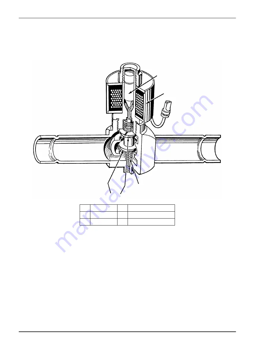
Modulation Valve Test
1.
Make sure that the unit has a modulation valve and that
the jumper is in the active position.
2.
Use the Service Test Mode to run the unit in Test Mode
MB1.0 (Modulation Cool Bypass Mode with modula-
tion valve set for 100% modulation).
2
3
4
5
6
1
1.
Outlet
4.
Inlet
2.
Armature
5.
Opening Spring
3.
Electric Coil
6.
Seats
3.
Check the suction pressure while the unit is in modula-
tion. The suction pressure should be 0 to 69 kPa
(0 to 10 psi).
4.
Remove fuse F31 from the relay board. The suction
pressure should rise 69 to 138 kPa (10 to 20 psi). If the
suction pressure does not rise, check the modulation
valve and the associated circuitry.
Summary of Contents for Super II SR+
Page 4: ......
Page 10: ...ii ...
Page 14: ...4 ...
Page 22: ...Unit Description Rev 6 98 12 Front View AEA1350 ...
Page 23: ...Unit Description Rev 6 98 13 Right Side Door Open AEA1351 ...
Page 24: ...Unit Description Rev 6 98 14 Left Side Doors Open AEA1352 ...
Page 26: ...Operating Instructions Rev 6 98 16 Control Box Cover AEA1354 ...
Page 34: ...24 ...
Page 42: ...Electronic Controls Rev 6 98 32 SOFTWARE REVISION 04XX ALARMS AEA1358 ...
Page 82: ...72 ...
Page 90: ...80 ...
Page 116: ...106 ...
Page 120: ...110 ...
Page 130: ...120 ...
Page 141: ...131 Schematic Diagram SBIII SII RMNII 30 SR MPIV ...
Page 142: ...132 Wiring Diagram SII SBIII RMN30 SR MPIV Page 1 of 4 ...
Page 143: ...133 Wiring Diagram SII SBIII RMN30 SR MPIV Page 2 of 4 ...
Page 144: ...134 Wiring Diagram SII SBIII RMN30 SR MPIV Page 3 of 4 ...
Page 145: ...135 Wiring Diagram SII SBIII RMN30 SR MPIV page 4 of 4 ...


