background image

Doc: 

FIT_S_US_EN_2019_rev4

     Rev: 

4

   Date: OCTOBER 14, 2019 

Manufacturer: 

DHOLLANDIA US, L.L.C. 

Tel : +1 704 629 5542  E-mail : [email protected] 

132 W Virginia Ave 

Bessemer City North Carolina, 28016 

website : www.dhollandia.com
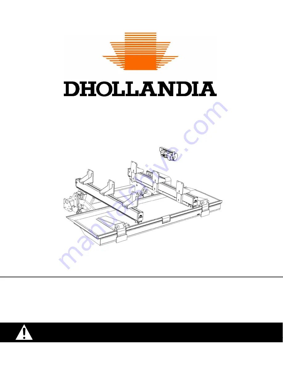


DH-S* 

INSTALLATION MANUAL 

Read the manual in its entirety before operating the liftgate 

Keep this manual in the vehicle cab, as reference for the driver and liftgate operator 

900

6,600lbs (400-3000kg) 

** Pictured: SM.20 liftgate 

Summary of Contents for DH-S Series

Page 1: ...o dhollandia com 132 W Virginia Ave Bessemer City North Carolina 28016 website www dhollandia com DH S INSTALLATION MANUAL Read the manual in its entirety before operating the liftgate Keep this manua...

Page 2: ...g tubes for DH SM R 1500 2000 kg 26 9 3 Differences for DH SSU R 2000 3000 kg and DH SK S 1000 2000 kg 28 9 4 Steel sliding tubes 29 9 5 Mounting the sliding tubes to the vehicle chassis 29 9 6 Adjust...

Page 3: ...upplied with liftgate 58 16 3 PDI checklist 1 2 60 16 4 Safe operator position on the platform 63 16 5 2 button portable control 64 16 6 Circuit breaker 68 16 7 Cab cut off switch 69 16 8 Electric and...

Page 4: ...ch if not avoided will result in death or serious injury white letters on red background WARNING indicates a potentially hazardous situation which if not avoided could result in death or serious injur...

Page 5: ...specialized customer requirements Therefore DHOLLANDIA reserves the right to alter product specifications without prior notice Such modifications might not have been included at the time this manual...

Page 6: ...sonal injury death or property damage that results from use of aftermarket or non OEM replacement parts for service or repair of the liftgate DHOLLANDIA disclaims liability for any personal injury dea...

Page 7: ...uctions are supplied as a separate manual with your liftgate You can also contact your national DHOLLANDIA distributor for the latest edition of this manual See page 5 for contact info Or download the...

Page 8: ...chinery and tools used for the installation Don t wear rings bracelets necklaces watches etc ALWAYS use the proper tool for the job Repair or replace worn or damaged tools before use Pay special atten...

Page 9: ...on system and don t require any welding See Appendix 2 for prescribed torque values Welding should be done by qualified personnel only and only to the extent allowed by the vehicle manufacturer Ensur...

Page 10: ...inders used to LIFT LOWER the lift arms the platform and its load 8 Tilt Cylinder hydraulic cylinders used to control the pitch of the lift platform 9 Mounting Brackets used to mount the sliding tubes...

Page 11: ...10 DHOLLANDIA 1 2 3 4 5 6 7 8 9 10 11 12 14 15 16 17 13 Figure 6 1...

Page 12: ...hicle floor applicable for the given arm length Chassis Total Height CTH Actual height from underside of chassis to top of the vehicle floor MFT Mounting height of lift frame under the vehicle measure...

Page 13: ...12 DHOLLANDIA Figure 6 2...

Page 14: ...ut Inside BCW Width of the cut outs for the lift arms and tilt cylinders Body Cut Width BLB Available mounting space for rear truck lights on outside of the tilt cylinders Body Light Boxes BFT Thickne...

Page 15: ...rking brake before starting Verify the installation kit is complete and that all parts needed to correctly fit the liftgate are present Compare the voltage of the vehicle batteries with the voltage of...

Page 16: ...n and while testing verify that the liftgate and its moving parts don t interfere with or cause damage to the vehicle systems e g to suspension braking system hydraulic and electrical circuits etc Do...

Page 17: ...imensions and maximum installation parameters indicated in above mentioned sources with the actual dimensions of the vehicle to verify compliance Verify that the actual vehicle dimensions comply with...

Page 18: ...ce MTG you could choose to fit liftgate higher above ground 2 In case of short mounting space LOF LOP you could choose to fit liftgate lower to the ground 3 To comply with RUP regulations you could ch...

Page 19: ...re 6 11 Refer to the TECHNICAL SUMMARY of the liftgate to define 1 The minimum body width BWO 2 The cut out dimensions BCW CHW determining the size of the mounting plates for the vehicle rear lights a...

Page 20: ...es covered by this manual are all actuated in out by means of a hydraulic motor see Figure 7 1 7 2 The hydraulic motor does not require any fixation of the drive system to the vehicle chassis In compa...

Page 21: ...TING JIGS There are 2 types of fitting jigs 1 set for the standard platforms Figure 8 1 and 1 set for option S245 S Figure 8 2 Measure the outside width across the lift arms This dimension corresponds...

Page 22: ...r and the platform during fitting Mount 2 strong tubes over the front edge of the platform Figure 8 5 Position the platform with the 2 tubes attached to it on the loading floor of the vehicle Slide th...

Page 23: ...10 With option S410 the liftgate is delivered fully pre mounted on a transport rack Figure 8 8 8 9 In this case the preparation is restricted to determining the start point L1 for the sliding tubes un...

Page 24: ...e doing this do not force either side of the frame higher or lower than the position it is taking naturally without exercising any special force From the side of the lift ensure the top face of the li...

Page 25: ...be mounted past the blocking edge of the end stop Figure 9 8 shows a trailer chassis with a platform buffer mounted to it inside the sliding tube See Figure 9 7 for the length L at which the bumper sh...

Page 26: ...ould hit the mudguard of the vehicle the air bag or any other parts of the vehicle prematurely the position of the end stops within the tubes or the length of the sliding tubes can be adjusted accordi...

Page 27: ...ting brackets 2 in Figure 9 13 is determined by the overhang dimension M 3 in Figure 9 13 When the platform is not mounted flush with the rear end of the vehicle correct the overhang dimension M accor...

Page 28: ...27 DHOLLANDIA 1 and 2 in Figure 9 14 show the mounting bracket too far to the rear and too far to the front respectively 4 threshold Figure 9 14 Figure 9 15...

Page 29: ...ckets is determined by the work position of the liftgate 1 in Figure 9 16 2 The position of the front mounting brackets 2 in Figure 9 16 is determined by the overhang dimension M 3 in Figure 9 16 When...

Page 30: ...the initial setup of the end stops these can be moved and adjusted accordingly The tubes can also be shortened in order to allow them to fit see Figure 9 18 When fastening the mounting brackets and th...

Page 31: ...lift frame again so as to have easy access to the area where the drills must be performed Drill the required holes into the chassis of the drill M value of the bolt 0 02 0 5mm apply sufficient anti c...

Page 32: ...ightened if required Ensure that all freshly made chassis perforations are properly deburred and that all metal work cutting drilling welding grinding is properly treated with an anti corrosive protec...

Page 33: ...th of the vehicle Liftgates concerned DH SMR DH SSUR Here the adjustment available on the mounting brackets is used to adapt the liftgate to the width of the lower flange of the I beam of the vehicle...

Page 34: ...urround welds over the top rear and bottom faces of the frame Figure 9 30 The torque fastenings of all bolts should be checked after completion of the compulsory static and dynamic weight tests at the...

Page 35: ...m open to a horizontal angle Continue to support the platform by means of a forklift hoist or gantry crane so you can continue working in the action radius of the platform in safety Connect the tilt c...

Page 36: ...The range TR should overlap the gear wheel both in working and stowing position This will prevent the gear wheel running off of the tooth rack Figure 10 8 If this is not the case loosen the bolts tha...

Page 37: ...een the loading floor of the vehicle and the platform in work position a bridge plate option S241 can be used see Figure 10 11 The same bridge plate can also be used on container chassis to adapt the...

Page 38: ...37 DHOLLANDIA End stops for retraction movement Slide plates Slide tubes Per Side 1x M16 8 8 195 Nm 143 lbf ft Figure 10 14 Figure 10 13 Figure 10 15 Figure 10 12...

Page 39: ...ide a soft means to store the platform under the vehicle chassis 2 To make the stow position of the platform comply with the legal bumper requirements see Figure 10 17 This can be a fabricated set of...

Page 40: ...ted inside the track of the sliding tubes behind the end stops for the work position 2 in Figure 10 19 and can be adjusted over a range H2 They can only be used when the end stops in the sliding tubes...

Page 41: ...he wiring diagrams in the appendices WARNING Slide the liftgate in and out several times in road position to ensure the setup of the tooth rack mounting brackets end stops and platform buffers work fo...

Page 42: ...the liftgate these can be downloaded from the DOWNLOAD section on our website www dhollandia com Please confirm you have reviewed the most up to date version of this manual prior to continuing If you...

Page 43: ...type of tube in the unit see Figure 11 2 Aluminum sliding tubes side mounted Aluminum sliding tubes under mounted Steel sliding tubes under mounted Plan the position of the control box prior to mount...

Page 44: ...43 DHOLLANDIA 11 3 ROUTING OF THE ELECTRIC CABLES A general schematic of how to correctly connect the batteries to the liftgate is provided in Figure 11 4 Figure 11 4...

Page 45: ...ure 11 Aluminum sliding tubes side mounted Figure 11 Aluminum sliding tubes under mounted Figure 11 Steel sliding tubes under mounted WARNING Verify the cable routing while executing all liftgate func...

Page 46: ...45 DHOLLANDIA Figure 11 6 Figure 11 8 Figure 11 7...

Page 47: ...raise the rear end of the vehicle off the ground or raise the vehicle air suspension to its maximum Starting from the platform in work position at the loading floor 1 Open the platform completely belo...

Page 48: ...after installation pictured on the following page and once in service with intervals as indicated in the maintenance manual Use a grease gun to pump grease in the lube fittings until a grease collar...

Page 49: ...48 DHOLLANDIA...

Page 50: ...49 DHOLLANDIA...

Page 51: ...m 2 Fit the platform flags to the underside of the flip over point 3 If applicable connect the flashing platform lights if not prewired and verify their function If the operator is allowed to travel u...

Page 52: ...act your regional DHOLLANDIA distributor See page 5 for contact info 3 The operator should comply with all affixed safety and instructions decals Be aware that the decals merely summarize the main poi...

Page 53: ...the vehicle body ALWAYS inspect the liftgate before using it DO NOT use liftgate if there are signs of bad maintenance subnormal wear or damage or if the platform surface is slippery DO NOT attempt t...

Page 54: ...rear of the vehicle Cabin switch in driver s cabin to switch electrical power to tail lift on off if so equipped For circuit breaker in liftgate battery compartment Or For main fuse in liftgate batte...

Page 55: ...pair is required If any unsafe condition exists or unusual noises or movements are noticed DO NOT use the liftgate and affix the WARNING LIFTGATE OUT OF SERVICE DO NOT ATTEMPT TO OPERATE sign provided...

Page 56: ...ticular liftgate or when ordering replacement parts 2 In addition to the liftgate type and serial number the various serial number labels provide additional information such as the maximum rated lift...

Page 57: ...hazard Hazard caused by tilting objects Hazard of falling from heights MANDATORY ACTION signs Contact your regional DHOLLANDIA distributor Consult the DHOLLANDIA website Download from DHOLLANDIA webs...

Page 58: ...ovision lever valve creating an emergency exit Unlock Disengage the mechanical locking system Lock Engage the mechanical locking system Switch ON the electrical power Switch ON the electrical power to...

Page 59: ...ICE WARNING Incorrect too soft or too hard tightening of mounting bolts can lead to accidental fall of the liftgate off the vehicle chassis A fall of the liftgate off the chassis can damage the liftga...

Page 60: ...x 2 143 lbs ft 210 lbs ft Fine M14 x 1 5 99 5 lbs ft 143 lbs ft M16 x 1 5 155 lbs ft 221 lbs ft M20 x 1 5 265 5 lbs ft lbs ft M24 x 2 332 lbs ft lbs ft Banjo Bolt Torque Specifications BSPP Banjo Bol...

Page 61: ...testing The extension plate side steps braces and dock bumpers are installed in conformance with the installation instructions All welding has been performed by qualified welders All articulation pin...

Page 62: ...sis body They cannot be damaged by rubbing squeezing etc None of the thermoplastic pipes has been damaged or marked during welding The cover of the pump unit is mounted and securely latched 5 Inspecti...

Page 63: ...f maximum load adjust the hydraulic pressure on the pressure relief valve so that the maximum rated lift capacity is just reached Seal the pressure relief valve after final adjustment with the provide...

Page 64: ...rm DHOLLANDIA recommends that the installer mounts a handgrip to the rear frame of the vehicle body Such handgrip will enable the operator to ALWAYS maintain 3 points of contact while lifting or lower...

Page 65: ...liftgate Make sure the cable 6 is protected against physical damage Run the cable inside the rear post of the vehicle body or mount a steel protection plate over it If the liftgate is equipped with a...

Page 66: ...65 DHOLLANDIA Figure 16 4...

Page 67: ...66 DHOLLANDIA A general wiring schematic for gravity down with the two button handheld control is shown in Figure 16 5 Figure 16 5...

Page 68: ...67 DHOLLANDIA For option OAE510 15 see Figure 16 6 below Figure 16 6...

Page 69: ...68 DHOLLANDIA 16 6 CIRCUIT BREAKER A resettable circuit breaker option is also available for the connection to the batteries Figure 16 9 Figure 16 9...

Page 70: ...the appropriate connection sequence in Figure 16 10 to properly connect the E0667 illuminated cab switch Figure 16 10 Figure 16 11 For orders that shipped with option OAE510 15 refer to Figure 16 12 t...

Page 71: ...commended battery cables and ground cables Recommended MIN cable sections for battery cables and ground cables Size electric motor Cable section 500 W 16 mm 5 AWG 1200 2200 W up to max 3300 lbs capaci...

Page 72: ...d uses the following abbreviations R starter solenoid for the DC motor M pump motor P pump unit T oil reservoir O self locking valve on the tilt cylinders U I 3 4 valve on the rear side of the pump un...

Page 73: ...72 DHOLLANDIA...

Page 74: ...73 DHOLLANDIA...

Page 75: ...74 DHOLLANDIA...

Page 76: ...75 DHOLLANDIA...

Page 77: ...76 DHOLLANDIA...

Page 78: ...77 DHOLLANDIA...

Page 79: ...y available hydraulic oil is used in the majority of DHOLLANDIA lifts sold for use in normal climate conditions This includes all countries excluding the Nordic countries suffering very cold winter cl...

Page 80: ...79 DHOLLANDIA 16 9 MOUNTING DIAGRAMS...

Page 81: ...80 DHOLLANDIA...

Page 82: ...DHOLLANDIA service agents Only authorized OEM DHOLLANDIA replacement parts should be used for all repairs Consult the separate MAINTENANCE AND REPAIR MANUAL for safety instructions maintenance guidel...

Reviews: