background image

A-5

Themis Computer

Connector Pinouts

VGA Display Port

A.5

VGA Display Port

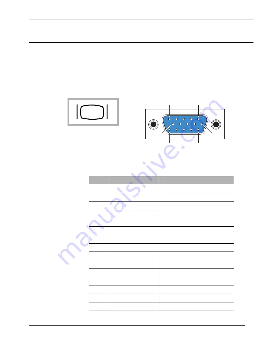
The RES-12DCX supports a single 15-pin (three 5-pin rows) 

female

 VGA graphics

display port connector on the rear I/O Panel (see 

Figure A-4

 for a connector pinout).

Pinout signal descriptions are listed in 

Table A-5

.  

Figure A-4.  

VGA Connector Pinout

Table A-5.  

VGA Connector Pinout Signal Descriptions

Pin

Signal

Description

1

RED

Red video

2

GREEN

Green video

3

BLUE

Blue video

4

ID2

Monitor ID bit 2

5

GND

Ground (HSync)

6

RED_RTN

Red return

7

GREEN_RTN

Green return

8

BLUE_RTN

Blue return

9

KEY

Key (no pin)

10

GND

Ground (VSync)

11

ID0

Monitor ID bit 0 

12

ID1 or SDA

Monitor ID bit 1

13

HSYNC

Horizontal sync

14

VSYNC

Vertical sync

15

ID3 or SCL

Monitor ID bit 3 

Symbol

JVGA1

6

10

15

11

1

5

VGA Display Port

Summary of Contents for RES-12DCX

Page 1: ...wo Intel Dual Core Quad Core 64 bit Xeon CPUs 1RU Server PCI Express PCI X Slots Gigabit Ethernet Serial ATA SATA Serial Attached SCSI SAS RAID IDE EIDE Floppy VGA USB RES 12DCX RES 12DCX Installation Manual Installation Manual ...

Page 2: ... r v e r R E S 1 2 D C X R E S 1 2 D C X 2 I n t e l D u a l C o r e Q u a d C o r e 6 4 b i t X e o n C P U s 1 R U S e r v e r R E S 1 2 D C X R E S 1 2 D C X 2 I n t e l D u a l C o r e Q u a d C o r e 6 4 b i t X e o n C P U s 1 R U S e r v e r R E S 1 2 D C X R E S 1 2 D C X 2 I n t e l D u a l C o r e Q u a d C o r e 6 4 b i t X e o n C P U s 1 R U S e r v e r R E S 1 2 D C X R E S 1 2 D C X...

Page 3: ...0 Eybens France Phone 33 476 14 77 80 Fax 33 476 14 77 89 Themis Computer Americas and Pacific Rim 47200 Bayside Parkway Fremont CA 94538 Phone 510 252 0870 Fax 510 490 5529 World Wide Web http www themis com RES 12DCX Installation Manual Version 1 1 March 2008 ...

Page 4: ...ication or disclosure by the United States Government is subject to the restrictions set forth in DFARS 252 227 7013 c 1 ii and FAR 52 227 19 TRADEMARKS and SERVICEMARKS Themis is a registered trademark of Themis Computer Inc Intel is a registered trademark of Intel Corporation Xeon is a trademark of Intel Corporation ATI is a trademark of Advanced Micro Devices Inc AMD Intersil is a registered tr...

Page 5: ...ch 2008 Modified Table 1 1 page 1 4 to include DC power supplies Modified Table 1 2 page 1 11 to define Overheat Fan Fail LED function Added a section German on Safety Instructions before the Table of Contents Assorted minor edits and changes throughout the manual Version 1 0 February 2008 ...

Page 6: ...onnected from the power source only when the power cord is disconnected from the power source Therefore the power cord and its connectors must always remain easily accessible Do not set up the device in the proximity of heat sources or in a damp location Make sure the device has adequate ventilation All plugs on the connection cables must be screwed or locked to the chassis housing The device is d...

Page 7: ...efore must not be opened If the enclosure of such a drive is opened invisible laser radiation is emitted Do not allow yourself to be exposed to this radiation The laser system meets the code of Federal Regulations 21 CFR 1040 for the USA and Canadian Radiation Emitting Devices Act REDR C 1370 Electrostatic Discharge ESD A sudden discharge of electrostatic electricity can destroy static sensitive d...

Page 8: ... pins leads or circuitry 5 Turn off power and input signals before inserting and removing connectors or test equipment 6 Keep the work area free of non conductive materials such as ordinary plastic as sembly aids and Styrofoam 7 Use field service tools such as cutters screwdrivers and vacuums that are con ductive 8 Always place drives and boards PCB assembly side down on the foam Instructions for ...

Page 9: ...hemis Computer 47200 Bayside Parkway Fremont CA 94538 U S A Tel Nr 001 510 252 0870 Fax Nr 001 510 490 5529 Allgemeine Bezeichnung Rechner Arbeitsplatz Handelsname Typenbezeichnung RES 12DCX Rugged Enterprise Server Typ Identikatoren RES 12DCX Server IR RES 12DCX Server RC CC Deutsche Version Nr 01 2008 vom 20 03 2008 ...

Page 10: ...lständige Trennung des Gerätes von der Netzspannung ist nur gewähr leistet wenn das Netzkabel vom Netz getrennt wird Aus diesem Grund muss das Netzkabel samt seinen Anschlüssen jederzeit leicht zugänglich sein Das Gerät darf nicht in der Nähe von Wärmequellen oder an einem feuchten Ort aufgestellt werden Achten Sie auf eine ausreichende Belüftung des Gerätes Alle Stecker an den Verbindungskabeln m...

Page 11: ...ffnen des Laufwerkgehäuses tritt unsichtbare Laserstrahlung aus Setzen Sie sich dieser Strahlung keinesfalls aus Das Lasersystem erfüllt die Anforderungen des Code of Federal Regulations 21 CFR 1040 für die USA und des Canadian Radiation Emitting Devices Act REDR C 1370 für Kanada Elektrostatische Entladung ESD Eine plötzliche elektrostatische Entladung kann empfindliche Geräte oder Mik roschaltun...

Page 12: ... den Kontakt mit Stiften Leitungen und Leiterbahnen 5 Schalten Sie vor dem Anschließen und Trennen von Steckverbindern oder Prüf geräten alle Spannungs und Signalquellen aus 6 Verwenden Sie am Arbeitsplatz keine nichtleitenden Materialien wie gewöhnliche Kunststoffmontagehilfen oder Styropor 7 Benutzen Sie leitende Werkzeuge z B Messer Schraubendreher und Staub sauger 8 Legen Sie Laufwerke und Pla...

Page 13: ...onal 1 8 1 1 1 7 IPMI Module Support 1 8 1 1 1 8 CPU Fan Auto Off in Sleep Doze Mode 1 8 1 1 2 ACPI Features 1 8 1 1 2 1 Suspend State Indicator 1 9 1 1 2 2 Main Switch Override 1 9 1 1 2 3 External Modem Ring On 1 9 1 1 2 4 Wake On LAN WOL 1 9 1 1 3 System LEDs 1 10 1 2 Chipset Overview 1 12 1 2 1 The Intel 5000P Memory Controller Hub MCH 1 12 1 2 2 The Intel 6321 ESB I O Controller Hub ICH 1 13 ...

Page 14: ... Removal 2 6 2 1 3 2 Disk Drive Installation 2 7 2 1 4 PCI Cards 2 8 2 1 4 1 Installation 2 11 2 1 5 Removable 38 mm Fan Housing 2 12 2 1 5 1 Removing the 38 mm Fan Housing 2 12 2 1 5 2 Installing a 38 mm Fan Housing 2 13 2 1 6 Lithium Battery 2 14 2 1 6 1 Removing the Lithium Battery 2 14 2 1 6 2 Installing a Lithium Battery 2 14 2 2 Rack Mounts 2 15 2 2 1 Mounting Brackets 2 15 2 2 2 Rack Mount ...

Page 15: ...Setup Utility C 2 C 2 Running Setup C 2 C 3 Main BIOS Setup C 3 C 3 1 Main Setup Features C 4 C 3 1 1 System Time C 4 C 3 1 2 System Date C 4 C 3 1 3 BIOS Date C 4 C 3 1 4 Legacy Diskette A C 4 C 3 1 5 IDE Channel 0 Master Slave IDE Channel 1 Master Slave SATA Port 2 and SATA Port 3 C 4 C 3 1 6 Parallel ATA C 5 C 3 1 7 Serial ATA C 5 C 3 1 8 Native Mode Operation C 5 C 3 1 9 SATA Controller Mode C...

Page 16: ...ding C 11 C 4 3 4 Reset Configuration Data C 11 C 4 3 5 Frequency for PCI X 7 MASS Mass Data Storage ZCR Zero Channel RAID C 11 C 4 3 6 Slot 6 PCI X 133MHz Slot E1 x8 Slot E2 x4 and Slot E3 x8 C 11 C 4 4 Advanced Chipset Control C 12 C 4 4 1 SERR Signal Condition C 12 C 4 4 2 4GB PCI Hole Granularity C 12 C 4 4 3 Memory Branch Mode C 12 C 4 4 4 Branch 0 Rank Interleaving Sparing C 12 C 4 4 5 Branc...

Page 17: ...echnology Only when supported by the CPU C 15 C 4 5 13 Intel EIST Support Only when supported by the CPU C 16 C 4 6 I O Device Configuration C 16 C 4 6 1 KBC Clock Input C 16 C 4 6 2 Serial Port A C 16 C 4 6 3 Base I O Address C 16 C 4 6 4 Interrupt C 16 C 4 6 5 Serial Port B C 17 C 4 6 6 Mode C 17 C 4 6 7 Base I O Address C 17 C 4 6 8 Interrupt C 17 C 4 6 9 Floppy Disk Controller C 17 C 4 6 10 Ba...

Page 18: ... Voltage Monitoring C 23 C 4 12 IPMI Only when an IPMI card is installed C 24 C 4 12 1 IPMI Specification Version C 24 C 4 12 2 Firmware Version C 24 C 4 12 3 System Event Logging C 24 C 4 12 4 Clear System Event Logging C 25 C 4 12 5 Existing Event Log Number C 25 C 4 12 6 Event Log Control C 25 C 4 12 7 BIOS POST Watch Dog C 25 C 4 12 8 OS Boot Watch Dog C 25 C 4 12 9 Timer for Loading OS Minute...

Page 19: ...lection D 2 D 2 2 2 Keyboard Selection D 3 D 2 2 3 Select Disk Partitioning Setup D 3 D 2 2 4 Automatic Partitioning D 5 D 2 2 5 Partitioning Your System D 6 D 2 2 6 Adding Partitions D 7 D 2 2 7 Boot Loader Configuration D 9 D 2 2 8 Advanced Boot Loader Configuration D 10 D 2 2 9 Network Configuration D 11 D 2 2 10 Firewall Configuration D 13 D 2 2 11 Time Zone Configuration D 14 D 2 2 12 Set Roo...

Page 20: ...xviii Themis Computer RES 12DCX Installation Manual ...

Page 21: ...ed to a Retainer Bracket 2 9 Figure 2 7 then inserted into Slots 6 and 7 of the Motherboard 2 9 Figure 2 8 PCI Riser Cards Installed in Slot 6 and Slot 7 2 10 Figure 2 9 Remove the Blank Panel for each PCI Card to be Installed 2 10 Figure 2 10 The RES 12DCX 38 mm Quadruple Fan Housing 2 12 Figure 2 11 Release the Two Screws Securing the 38 mm Fan Housing 2 13 Figure 2 12 The RES 12DCX Lithium Batt...

Page 22: ... Figure D 9 Network Configuration C 11 Figure D 10 Editing a Network Device C 12 Figure D 11 Firewall Configuration C 13 Figure D 12 Time Zone Configuration C 14 Figure D 13 Set Root Password C 15 Figure D 14 Package Installation Defaults C 16 Figure D 15 Package Group Selection C 17 Figure D 16 Package Group Details C 18 Figure C 1 The Main BIOS Setup Menu C 3 Figure C 2 The Advanced BIOS Setup M...

Page 23: ...X 1 17 Table 2 1 RES 12DCX Memory Modules 2 3 Table 2 2 Optimized DIMM Configurations 2 3 Table A 1 PS 2 Keyboard Mouse Connector Pinout and Signal Descriptions A 1 Table A 2 USB Connector Pinout Signal Descriptions A 2 Table A 3 COM 1 COM 2 Serial Port Pinout Signal Descriptions A 3 Table A 4 Gigabit Ethernet Connector Pinout Signals and LED Interpretation A 4 Table A 5 VGA Connector Pinout Signa...

Page 24: ...xxii Themis Computer RES 12DCX Installation Manual ...

Page 25: ... dual core quad core 64 bit Intel XeonTM CPUs These instructions are intended for an experienced system administrator with a knowledge of both networking and high speed server systems The 1RU high 1 75 RES 12DCX has been designed to fit into a standard 19 rack and is provided with rack mount brackets without handles Optional rack mount brackets with handles and optional rack mount slides are also ...

Page 26: ...ES 12DCX is based on the functionality and capability of the Intel 5000P Blackford chipset which consists of the following three devices Intel 5000P Memory Controller Hub MCH Intel 6321 ESB2 Enterprise South Bridge 2 I O Controller Hub ICH Intel 6700PXH 64 bit PCI X Hub PXH V An overview of RES 12DCX design and specifications is given in Chapter 1 Over view and Specifications of this manual Websit...

Page 27: ...erator or equipment This may involve but is not restricted to heavy equipment or sharp objects To reduce the risk follow the instructions accompanying this symbol Warning A warning describes a procedure or action that may cause injury to the operator or equipment as a result of hazardous voltages To reduce the risk of elec trical shock and danger follow the instructions accompanying this symbol Si...

Page 28: ...xxvi Themis Computer RES 12DCX Installation Manual ...

Page 29: ...bration environments The RES 12DCX supports single or dual Intel 771 pin LGA XeonTM 64 bit dual quad core processors each 2 67 1 86 GHz with a 1333 MHz system bus and contains a combination of computer and graphics intensive and diverse I O capabilities ideal for a variety of military aerospace and commercial telecommunications applications Figure 1 1 RES 12DCX with Rack Mounts General Section Cha...

Page 30: ... Connector RJ45 Connector 2 67 GHz Dual Core 1 86 GHz Quad Core LPC Bus Kumeran Interface 64 bit Intel XeonTM Processor Dual Quad Core 2 67 GHz Dual Core 1 86 GHz Quad Core Notes LSB Least Significant Bit MSB Most Significant Bit SO DIMM Small Outline Dual In Line Memory Module PCI E PCI Express IPMI Intelligent Platform Management Interface LPC Low Pin Count ATI ES1000 VGA Graphics Controller Fir...

Page 31: ...cards one 133 MHz Slot 6 and one 100 MHz ZCR Slot 7 One PCI Express x8 card and one 100 MHz 64 bit Slot 7 or 133 MHz 64 bit Slot 6 PCI X card see Figure 1 3 Figure 1 3 External Features of the RES 12DCX Front and Rear Front View AC Power Socket 3 prong NEMA 15 Power Supply with System Power On Off Switch CD RW DVD ROM Combo Slimline Drive 17 43 2 cm 19 with Rack Mounts 1 75 1RU 20 50 8 cm deep Rea...

Page 32: ...Hz front side system bus speed z On board Voltage Regulator Module per processor Chipset z Intel chipset Memory Controller Hub MCH 6700 PCI X Hub PXH V Enterprise SouthBridge 6321 I O Controller Hub ICH Memory z Eight 240 pin DIMM sockets supporting up to 32 GB of registered ECC DDR2 FBD 667 533 SDRAM Expansion slots The following 2 PCI slots are horizontally located on a PCI Riser Card one Riser ...

Page 33: ...e only z 1 SIM SO DIMM IPMI Intelligent Platform Management Interface socket Operating temperature z 0 C to 50 C Shock endurance z 25G 20 msec duration Dimensions z 1 75 1RU high 17 43 2 cm wide 19 48 3 cm with mounting brackets 20 50 8 cm deep Rack mount brackets and slides z Choice of rack mount brackets with handles z Optional rack mount slides One power supply AC or DC AC Output z 650 watts au...

Page 34: ...8 DC also available CPU 2 with Fan CPU 1 with Fan Note on PCI Slot Availability Because of the 1RU height restriction of the RES 12DCX PCI cards must be installed in the horizontal position through the use of a PCI Riser Card As a result only 2 PCI cards can be installed See Chapter 2 for more details Four 38 mm Fans PCI Slot 7 Riser Card SIM SO DIMM IPMI Socket PCI Express x8 PCI X 64 bit 133 MHz...

Page 35: ...cooling fans four 38 mm fans within one fan assembly at the front of the system one on each CPU and two within the single power supply The PC health monitor utility can be used to check the RPM status of cooling fans The onboard CPU and chassis fans are controlled by Thermal Management via the BIOS under Hardware Monitoring in the Advance Setting 1 1 1 4 Environmental Temperature Control The therm...

Page 36: ...an optional Intelligent Platform Management Interface IPMI module This invaluable health monitoring tool provides full SNMP includ ing SNMP trap some power cycle functions reboot and graceful shutdown and the ability to control other servers This module must be installed at the factory Detailed information on IPMI may be obtained from the following website http www intel com design servers ipmi 1 ...

Page 37: ...ystem enter a SoftOff state The monitor is suspended and the hard drive will spin down Pressing the power button again will cause the system to awaken During the SoftOff state the ATX power supply provides only enough power to keep the minimum required circuitry alive If you want to turn the power off com pletely in the event of a system malfunction for example depress and hold the power button fo...

Page 38: ...WOL capability In addi tion an onboard LAN controller can also support WOL without any connection to the WOL header The 3 pin WOL header is intended to be used with a LAN add on card only Wake On LAN must be enabled in BIOS 1 1 3 System LEDs All RES 12DCX system LEDs are located on the front panel see Figure 1 5 LEDs are described in Table 1 2 on page 1 11 Figure 1 5 RES 12DCX System LEDs Reset Sw...

Page 39: ...activity on LAN 2 NIC1 Gbit Ethernet z Indicates network activity on LAN 1 Overheat Fan Fail z Warns that the system is exceeding specified temperature parameters Symbol Rear Panel LEDs Description N A LAN1 and LAN2 Each Ethernet port contains two LEDs z The color of the left LED when facing the port indicates the LAN connection speed Off No connection or 10 Mbps Green 100 Mbps Amber 1 Gbps z The ...

Page 40: ...lti processing across two independent front side bus interfaces Each front side bus uses a 64 bit wide 1 333 GHz data bus that transfers data at 10 7 GB sec for a total bandwidth of 21 3 GB sec The MCH provides four channels of Fully Buffered DIMM FB DIMM memory Each of these channels can support up to four Dual Ranked FB DIMM DDR2 DIMMs FB DIMM memory channels are organized in to two branches for...

Page 41: ...ler Hub platform can support the Full on Stop Grant Suspend to RAM Suspend to Disk and Soft Off power man agement states Through the use of the integrated LAN functions the Intel 6321 ESB I O Controller Hub also supports Alert Standard Format for remote management 1 2 3 The Intel 6700 PCI X 64 bit Hub PXH V The Intel 6700 PCI X 64 bit hub PXH V attaches directly to the MCH through a point to point...

Page 42: ...s UARTs Each UART includes a 16 byte send receive FIFO a programmable baud rate generator complete modem control capability and a processor interrupt system Both UARTs provide legacy speed with baud rates of up to 115 2 Kbps as well as an advanced speed with baud rates of 250K 500K or 1 Mb s for higher speed modems The Super I O supports one PC compatible printer port SPP Bi directional Printer Po...

Page 43: ...for the shipping container and one AC power cord z The manual and associated shipping paperwork weighs approx imately 1 lb 0 5 kg 19 Rack Mountable with Slide capability z Left and right rack mount tabs 3 screws each included with chassis Rack mount slides are optional Temperature Operating Non Operating z 0 C to 50 C z 40 C to 70 C Relative Humidity Operating Non Operating z 8 to 90 non condensin...

Page 44: ...to 63 Hertz source Filtered and fused internal AC is supplied from a rear mounted power connection DC Power Supply The DC power supply has a 300 watt output capacity 1 3 2 2 Output Voltage The RES 12DCX provides output voltages that are split between 3 3V 5V 5Vsb 12V and 12V rails Table 1 4 RES 12DCX Electrical Specifications Parameter Description Input Power z 390 watts Input Current z 8 amperes ...

Page 45: ... at 20 msec duration 1 3 3 2 Electrostatic Discharge The RES 12DCX is designed to tolerate electrostatic pulses up to 15 kilovolts KV with no impact on system operation 1 3 3 3 Noise Level Typical noise levels emitted by the RES 12DCX are outlined in Table 1 5 The chas sis is installed with four 38 mm fans contained side by side in a single fan assembly Table 1 5 Typical Noise Levels of the RES 12...

Page 46: ...pproximate weight of a manual and associated shipping paperwork is one pound 0 5 kg Therefore both the shipping container and a fully installed RES 12DCX including power cord manual and associated paperwork weigh under 28 pounds 12 7 kg 1 4 1 Rack Mount Slides Optional Rack Mount Slides can be mounted on each side of the RES 12DCX for the pur pose of sliding the unit in and out of a rack Mounting ...

Page 47: ...drive skip the next section and proceed directly to page 2 6 Replacement of motherboard components require removal of the chassis protective cover 2 1 1 Remove Protective Top Cover To access a motherboard component open the RES 12DCX as follows Caution Use industry standard ESD grounding techniques when handling all components Wear an antistatic wrist strap and use an ESD protected mat Store ESD s...

Page 48: ...e cover by sliding it toward the rear until it is free of these chassis slots 3 Store the cover in a safe place until it is replaced 4 Proceed to the appropriate section to install or replace a memory module page 2 3 PCI card page 2 8 38 mm fan housing page 2 12 or lithium battery page 2 14 Figure 2 1 Remove the RES 12DCX Protective Access Cover Loosen the 2 captive access cover screws A B Rear Vi...

Page 49: ...recommended that you do not mix memory modules of different speeds and sizes If DIMMs of different speeds have been installed verify that the BIOS setup is configured for the fastest speed of RAM used Make sure that the correct type of SDRAM is being used see Table 2 1 Other types of SDRAM are not supported Table 2 1 RES 12DCX Memory Modules RES 12DCX Memory FBD Standard Capacity Speed Peak Transf...

Page 50: ...ains how to install the DDR2 FBD Memory Modules 1 Determine the location of the slot into which the Memory Module will be in stalled see Figure 2 2 Figure 2 2 Memory Module Slot Location Front Bank 4 DIMM 4A DIMM 4B DIMM 4A DIMM 4B DIMM 3A Bank 3 DIMM 3B DIMM 2A Bank 2 DIMM 2B DIMM 1A Bank 1 DIMM 1B ...

Page 51: ...ector 3 Before inserting a new memory module into the vacant slot make sure that the two latches are pulled outward away from the center of the slot With the latches in the outward position gently insert the new module verti cally into its slot and press firmly downward until it snaps into place Figure 2 3 Memory Module Removal downward outward at each end Press latch Note Make sure the memory mod...

Page 52: ...ptive screw of the drive latch handle until it swings away from the chassis see B 4 Carefully pull the latch handle see C until the drive has cleared the chassis The drive will automatically disconnect from its backplane connector when pulled forward Caution When pulling the hard disk drive from the chassis hold it at the bottom to prevent it from falling and damaging the drive Figure 2 4 RES 12DC...

Page 53: ...ll the drive incorrectly into its slot 3 Push the drive toward the rear DO NOT CLOSE the latch handle while push ing until the drive is flush with the front of the chassis The handle will swing closed when it comes into contact with the RES 12DCX chassis 4 When the drive is fully inserted into its slot push the latch handle closed and secure the captive screw to the chassis Caution When in the clo...

Page 54: ...R Slot 7 One PCI Express x8 card and one 100 MHz 64 bit Slot 7 or one 133 MHz 64 bit Slot 6 PCI X card Note The PCI Riser Cards that are installed on the RES 12DCX motherboard depend on the type of PCI card that will be supported Figure 2 5 Positioning of the RES 12DCX PCI Riser Cards PCI X Slot 100 MHz ZCR Support PCI X Slot 133 MHz Slot 6 Slot 7 PCI Express Slot x8 PCI Express Slot x8 PCI Slots ...

Page 55: ... Bracket Figure 2 7 then inserted into Slots 6 and 7 of the Motherboard Retainer Bracket Slot 6 Riser Card Slot 7Riser Card PCI Card Slot PCI Card Slot Top View of PCI Slot 6 and Slot 7 on Motherboard Slot 6 Slot 7 Top View of Retainer Bracket with Riser Cards attached Retainer Bracket Slot 6 Riser Card Slot 7 Riser Card A B ...

Page 56: ...d Slot 7 Figure 2 9 Remove the Blank Panel for each PCI Card to be Installed PCI Card Slot Slot 7 PCI Card Slot Slot 6 PCI Riser Card Retainer Bracket Blank PCI Card Panel Slot 6 Blank PCI Card Panel Slot 7 Panel Screw Panel Screw Panel Screw Panel Screw PCI Riser Card Retainer Bracket Mounting Screws ...

Page 57: ...rough Figure 2 8 3 Install a PCI card in an available slot on the Riser Card securing its I O face plate to the rear of the chassis with the Phillips screws removed in Step 1 4 If necessary install a second PCI card in the second available slot securing its I O faceplate to the rear of the chassis with the Phillips screws removed in Step 1 5 Attach any internal I O cables to the installed PCI card...

Page 58: ... With a Phillips screwdriver loosen the two screws holding the 38 mm qua druple fan housing to the RES 12DCX chassis see Figure 2 11 page 2 13 until the housing is released 3 Six twisted wires three pairs form the cabling system of the fan housing Carefully remove the 3 pin fan cable connector from its counterpart connec tor on the motherboard Remember where the cable was attached for later re con...

Page 59: ...he bottom of the chassis see Figure 2 11 2 Connect the 3 pin fan cable connector from the new 38 mm fan housing to the original connectors from which the replaced fan housing cables were re moved The cable connector is keyed to prevent incorrect cable insertion 3 Reinsert and tighten the two screws at the bottom of the fan housing with a Phillips screwdriver until the fan housing is firmly secured...

Page 60: ...the battery lifts out of its socket 3 Remove the old battery and replace with a new battery see next section 2 1 6 2 Installing a Lithium Battery Perform the following steps to insert a new lithium battery 1 Tilt the replacement battery into the empty socket so that it is angled under the battery latch see B Figure 2 12 2 Carefully press down on the battery until it clicks firmly into place Figure...

Page 61: ...k mount slides have been installed on the sides of the chassis see following section 2 2 2 Rack Mount Slides Optional Rack Mount Slides can be mounted on each side of the RES 12DCX for the purpose of sliding the unit in and out of a rack Mounting slides are optional and should be ordered at the time your system is purchased To learn how to install rack mount slides refer to Appendix B Rack Mount S...

Page 62: ...ket on the power supply see Figure 2 14 2 3 2 Turning the System On 1 Plug the AC power cord already attached to the RES 12DCX power supply into a live AC outlet 2 Push the system power on off switch on the front of the RES 12DCX see Figure 2 15 This will cause the system POWER LED to light green Figure 2 14 AC Power Socket on the Rear of the RES 12DCX AC Power Socket Figure 2 15 System Power Swit...

Page 63: ... 4 Turn the system on see previous section 2 3 3 2 Linux Installation The subject of installing the Linux operating system onto the RES 12DCX is detailed in Appendix D Red Hat Enterprise Linux Installation 2 3 4 Turning the System Off 1 To turn the RES 12DCX power off press and hold the system power on off button see Figure 2 15 for at least four 4 seconds This will shut down the system and turn o...

Page 64: ...2 18 Themis Computer RES 12DCX Installation Manual ...

Page 65: ... Keyboard and Mouse The RES 12DCX rear I O Panel provides a 6 pin female mini DIN connector for the PS 2 keyboard and another for the PS 2 mouse A pinout and signal descriptions for both connectors are defined in Table A 1 Table A 1 PS 2 Keyboard Mouse Connector Pinout and Signal Descriptions Pin Signal Description 1 Keyboard Mouse data 2 N C 3 Ground 4 Vcc 5 Keyboard Mouse clock 6 N C 1 5 3 2 4 6...

Page 66: ...for connector pinouts four optional USB ports USB 2 3 4 and 5 accessed from on board motherboard headers are not supported by the RES 12DCX Pinout signal descriptions are listed in Table A 2 Figure A 1 USB Ports A and B Connector Pinout Table A 2 USB Connector Pinout Signal Descriptions Pin Signal Name Pin Signal Name 1 5V 3 PO 2 PO 4 GND USB Ports Symbol USB 1 Port B USB 0 Port A JUSB1 ...

Page 67: ... described in Table A 3 Figure A 2 COM 1 COM 2 Serial Port Connector Pinout Symbol JCOM1 Rear I O Panel JCOM2 Header Motherboard 1 2 3 4 5 6 7 8 9 COM 1 COM 2 Table A 3 COM 1 COM 2 Serial Port Pinout Signal Descriptions Pin Signal Name Signal Definition Pin Signal Name Signal Definition 1 DCD Data Carrier Detect 6 DSR Data Set Ready 2 RXD Receive Data 7 RTS Request To Send 3 TXD Transmit Data 8 CT...

Page 68: ...e A 3 LAN 1 LAN 2 Gigabit Ethernet Connector Pinout Symbol Link LED Activity LED 1 8 Table A 4 Gigabit Ethernet Connector Pinout Signals and LED Interpretation Pin Signal Description LED LED Colora Interpretation 1 TRD0 Transmit Receive Data 0 Amber Green Left Link Speed OFF No Connection or 10 Mb s 2 TRD0 Transmit Receive Data 0 3 TRD1 Transmit Receive Data 1 Green 100 Mb s 4 TRD2 Transmit Receiv...

Page 69: ... Figure A 4 VGA Connector Pinout Table A 5 VGA Connector Pinout Signal Descriptions Pin Signal Description 1 RED Red video 2 GREEN Green video 3 BLUE Blue video 4 ID2 Monitor ID bit 2 5 GND Ground HSync 6 RED_RTN Red return 7 GREEN_RTN Green return 8 BLUE_RTN Blue return 9 KEY Key no pin 10 GND Ground VSync 11 ID0 Monitor ID bit 0 12 ID1 or SDA Monitor ID bit 1 13 HSYNC Horizontal sync 14 VSYNC Ve...

Page 70: ...otherboard has 16 LED status indica tors associated with the SAS ports eight LEDs to indicate the presence of an SAS connector and eight LEDs to indicate SAS activity see Figure A 6 on page A 7 Figure A 5 SAS Connector Pinout Symbol SAS Ports 4 7 JSM2 A18 A1 B18 B1 Table A 6 SAS Connector Pinout Signal Descriptions Pin Signal Pin Signal A1 GROUND B1 GROUND A2 RX 0 B2 TX 0 A3 RX 0 B3 TX 0 A4 GROUND...

Page 71: ... SATA2 JS3 JS4 SATA5 SATA4 JS5 JS6 Fan5 Front Fan4 Fan3 JPW2 4 pin PWR 3rd PWR Fail Buzzer JPWF J18 JVGA1 4 k n a B 3 k n a B E3x8 SXB 1 L P J 2 L P J JSM2 WOR JBT1 GLAN CTRLR VGA CTRLR BIOS DIMM 3A DIMM 3B DIMM 2A DIMM 2B 2 k n a B 1 k n a B DIMM 1A DIMM 1B JF1 CPU2 JIPMI SIMSO COM2 PCI X 100MHz ZCR SXB E1x8J41 J42 J43 JI 2 C2 PWLEDSPK JD1 LE1 JOH1 J7 SGPIO1 SGPIO2 O I S Pre 4 7 Act 4 7 IPMBJ10 J...

Page 72: ...A 8 Themis Computer RES 12DCX Installation Manual ...

Page 73: ...uminum slides may require different mounting holes and may also share one or more mounting holes Dimensions of the screw hole patterns on the sides of the RES 12DCX chassis for installing rack mount slides are shown in Figure B 1 The required holes for a spe cific steel or aluminum slide will have to be measured before installation Figure B 1 Screw Locations for Rack Mount Slides 455 8 Note All di...

Page 74: ...r slide brackets to the outside slide section using the screws washers and nuts provided with the slide kit 4 With all slide brackets securely attached to both the right and left outside slide sections install both sections to the inside right and inside left of a 19 rack with two bolts per bracket making sure there is adequate room for the 1RU height 1 75 of a RES 12DCX system 5 Carefully insert ...

Page 75: ... B 3 B Figure B 2 RES 12DCX Rack Mount Slide Installation 455 8 Note All dimensions are given in millimeters mm 439 9 354 2 265 6 217 4 52 6 39 9 164 1 100 95 22 A Side View of RES 12DCX Slide Installation B RES 12DCX Rack Mount Slide Installation ...

Page 76: ...Themis Computer RES 12DCX Installation Manual B 4 ...

Page 77: ... the CMOS The CMOS memory requires very little electrical power When the computer is turned off a backup battery pro vides power to the CMOS logic enabling it to retain system parameters Each time the computer is powered on the computer is configured with the values stored in the CMOS logic by the system BIOS which gains control at boot up Note Due to periodic changes to the BIOS some settings may...

Page 78: ...for each parameter setting in the Setup utility C 2 Running Setup The BIOS setup options described in this section are selected by choosing the appro priate text from the main BIOS Setup screen see Figure C 1 on page C 3 The screen display is often all you need to understand how to set the options When the computer is first powered on the Phoenix BIOS is immediately acti vated While the BIOS is in...

Page 79: ...he Up Down arrow keys to move among the different settings in each menu Use the Left Right arrow keys to change the options for each setting The icon X indicates a submenu With the item highlighted press the Enter key to access the submenu Press the Esc key to exit the CMOS Setup Menu The next section describes in detail how to navigate through the menus Figure C 1 The Main BIOS Setup Menu ...

Page 80: ...8MB 3 5 in C 3 1 5 IDE Channel 0 Master Slave IDE Channel 1 Master Slave SATA Port 2 and SATA Port 3 These settings allow the user to set the parameters of IDE Channel 0 Master Slave IDE Channel 1 Master Slave IDE Channel 2 Master IDE Channel 3 Master slots Hit Enter to activate the following sub menu screen for detailed options of these items Set the correct configurations accordingly The items i...

Page 81: ...st PIO2 Fast PIO3 Fast PIO4 FPIO3 DMA1 and FPIO4 DMA2 Ultra DMA Mode This option allows the user to select Ultra DMA Mode The options are Disabled Mode 0 Mode 1 Mode 2 Mode 3 Mode 4 and Mode 5 C 3 1 6 Parallel ATA This setting allows the user to enable or disable the function of Parallel ATA The options are Channel 0 and Channel 1 C 3 1 7 Serial ATA This setting allows the user to enable or disabl...

Page 82: ...tem memory is recognized as being present in the system C 3 1 11Extended Memory This display informs you how much extended memory is recognized as being present in the system Note The Enhanced mode is supported by the Windows 2000 OS or a later ver sion Note For the Windows OS environment use the RAID driver if this feature is set to Enabled When this item is set to Enabled the item ICH RAID Code ...

Page 83: ...s that can be accessed by highlighting the item and press ing Enter C 4 1 X Boot Features Access the Boot Features submenu to make changes to the following settings C 4 1 1 Quick Boot Mode If enabled this feature will speed up the POST Power On Self Test routine by skip ping certain tests after the computer is turned on The settings are Enabled and Dis abled If Disabled the POST routine will run a...

Page 84: ...mediately as soon as the user hits the power button If set to 4 sec the system will power off when the user presses the power button for 4 seconds or longer The options are instant off and 4 sec override C 4 1 6 Resume On Modem Ring Select On to wake your system up when an incoming call is received by your modem The options are On and Off C 4 1 7 Power Loss Control This setting allows you to choos...

Page 85: ...lock 0 512K to be cached written into a buffer a storage area in the Static DROM SDROM or to be written into L1 L2 cache inside the CPU to speed up CPU oper ations Select Uncached to disable this function Select Write Through to allow data to be cached into the buffer and written into the system memory at the same time Select Write Protect to prevent data from being written into the base memory ar...

Page 86: ...ect Write Back to allow CPU to write data back directly from the buffer without writing data to the System Memory for fast CPU data processing and operation The options are Uncached Write Through Write Protect and Write Back C 4 2 6 Discrete MTRR Allocation If enabled MTRRs Memory Type Range Registers are configured as distinct sep arate units and cannot be overlapped If enabled the user can achie...

Page 87: ...u for each of the settings to make changes to the following Option ROM Scan When enabled this setting will initialize the device expansion ROM The options are Enabled and Disabled Enable Master This setting allows you to enable the selected device as the PCI bus master The options are Enabled and Disabled Latency Timer This setting allows you to set the clock rate for Bus Master A high priority hi...

Page 88: ...s data correction by maintaining two copies of data in two branches Single Channel 0 allows a single DIMM population during system manufacturing The options are Interleave Sequential Mirroring and Sin gle Channel 0 C 4 4 4 Branch 0 Rank Interleaving Sparing Select enable to enable the functions of Memory Interleaving and Memory Sparing for Branch 0 Rank The options for Memory Interleaving are 1 1 ...

Page 89: ...ference caused by the components and will attempt to decrease the interference whenever needed The options are Enabled and Disabled C 4 4 10Enabling Multi Media Timer Select Yes to activate a set of timers that are alternative to the traditional 8254 timers for the OS use The options are Yes and No C 4 4 11USB Function Select Enabled to enable the function of USB devices specified The settings are...

Page 90: ...ocessor s Second Core and beyond Please refer to Intel s website for more information The options are Disabled and Enabled C 4 5 5 Machine Checking Only when supported by the CPU Set to Enabled to activate the function of Machine Checking and allow the CPU to detect and report hardware machine errors via a set of model specific registers MSRs The options are Disabled and Enabled C 4 5 6 Thermal Ma...

Page 91: ...en supported by the CPU The CPU fetches the cache line for 64 bytes if this option is set to Disabled The CPU fetches both cache lines for 128 bytes as comprised if Enabled The options are Disabled and Enabled C 4 5 10Hardware Prefetch Only when supported by the CPU Set to this option to enabled to enable the hardware components that are used in con junction with software programs to prefetch data...

Page 92: ...ake changes to the following settings C 4 6 1 KBC Clock Input This setting allows you to select clock frequency for KBC The options are 6MHz 8MHz 12MHz and 16MHz C 4 6 2 Serial Port A This setting allows you to assign control of serial port A The options are Enabled user defined Disabled and Auto BIOS or OS controlled C 4 6 3 Base I O Address This setting allows you to select the base I O address ...

Page 93: ...pt This setting allows you to select the IRQ interrupt request for serial port B The options are IRQ3 and IRQ4 C 4 6 9 Floppy Disk Controller This setting allows you to assign control of the floppy disk controller The options are Enabled user defined Disabled and Auto BIOS and OS controlled C 4 6 10Base I O Address This setting allows you to s elect the base I O address for the floppy port The opt...

Page 94: ... All DMI Event Logs Select Yes and press Enter to clear all DMI event logs The options are Yes and No C 4 8 X Console Redirection Access the submenu to make changes to the following settings C 4 8 1 COM Port Address This item allows you to specify which COM port to redirect the console to Onboard COM A or Onboard COM B This setting can also be Disabled C 4 8 2 BAUD Rate This item allows you to sel...

Page 95: ...emperature Threshold This option allows the user to set a CPU temperature threshold that will activate the alarm system when the CPU temperature reaches this pre set temperature threshold The options are 70o C 75o C 80o C and 85o C Highlight the entry and hit Enter to see monitor data for the following items CPU1 Temperature CPU1 Second Core Temperature CPU2 Temperature CPU2 Second Core Temperatur...

Page 96: ... control function to allow the onboard fans to con stantly run at full speed 12V all the time The Options are 1 Disable 2 3 pin Server 3 3 pin Workstation C 4 9 3 Voltage Monitoring The following items will be monitored and displayed P12V_VR0 P12V_VR1 FSB VTT PXH V Vcore ES2B Vcore CPU1 Vcore CPU2 Vcore P3V3 Note In the Windows OS environment the Supero Doctor III settings take pre cedence over th...

Page 97: ...the BIOS will automatically display the status of the fans indicated in this item C 4 10 2Fan Speed Control Modes This feature allows the user to decide how the system controls the speeds of the onboard fans The CPU temperature and the fan speed are correlative When the CPU on die temperature increases the fan speed will also increase and vise versa If the option is set to 3 pin fan the fan speed ...

Page 98: ...perature Monitoring If supported by the CPU Highlight the entry and hit Enter to see monitor data for the following PECI Plat form Environment Control Interface items PECI Agent 1 Temperature PECI Agent 2 Temperature PECI Agent 3 Temperature Note In the Windows OS environment the Supero Doctor III settings take pre cedence over the BIOS settings When first installed Supero Doctor III adopts the te...

Page 99: ...able to disable the fan speed control function to allow the onboard fans to run at the full speed 12V all of the time The Options are 1 Disable 2 3 pin Server 3 3 pin Workstation C 4 11 4Voltage Monitoring The following items will be monitored and displayed Vcore A Vcore B 12V P1V5 3 3V 12V 5Vsb 5VDD P_VTT Vbat Note In the Windows OS environment the Supero Doctor III settings take pre cedence over...

Page 100: ... current IPMI Version C 4 12 2Firmware Version This item displays the current Firmware Version C 4 12 3System Event Logging Select Enabled to enable IPMI Event Logging When this function is set to Disabled the system will continue to log events received via system interface The options are Enabled and Disabled Figure C 3 The Advanced BIOS Setup IPMI Submenu ...

Page 101: ...e options are Enabled and Disabled C 4 12 7BIOS POST Watch Dog Set to Enabled to enable POST Watch Dog The options are Enabled and Disabled C 4 12 8OS Boot Watch Dog Set to Enabled to enable OS Boot Watch Dog The options are Enabled and Dis abled C 4 12 9Timer for Loading OS Minutes This feature allows the user to set the time value in minutes for the previous item OS Boot Watch Dog by keying in a...

Page 102: ...tions display the System Event Log SEL and System Event Log SEL in List Mode Items include SEL System Event Log Entry Number SEL Record ID SEL Record Type Time Stamp Generator ID SEL Message Revision Sensor Type Sensor Number SEL Event Type Event Description SEL Event Data Figure C 4 The System Event Log Submenu ...

Page 103: ...Setup Utility Advanced Setup C 4 14 X Realtime Sensor Data This feature displays information from motherboard sensors such as temperatures fan speed and voltages of various components Figure C 5 The Realtime Sensor Data Submenu ...

Page 104: ...ing options are displayed by highlighting the entry using the arrow keys and pressing Enter All Security BIOS settings are described in this section C 5 1 Supervisor Password Is This entry displays whether a supervisor password has been entered for the system Clear means such a password has not been used and Set means a supervisor pass word has been entered for the system Figure C 6 The BIOS Setup...

Page 105: ...er key When prompted type the supervisor password in the dialogue box to set or to change the supervisor password which allows access to the BIOS C 5 4 Set User Password When the item Set User Password is highlighted hit the Enter key When prompted type the user password in the dialogue box to set or to change the user password which allows access to the system at boot up C 5 5 Password on Boot Th...

Page 106: ... boot functions for the devices included in the candidate list above are currently disabled Use a key or a key to move the device up or down Use the f key or the r key to specify the type of an USB device either fixed or removable You can select one item from the boot list and hit the x key to remove it from the list of bootable devices to make its resource available for other bootable devices Sub...

Page 107: ...igure C 8 All Exit BIOS settings are described in this section C 7 1 Exit Saving Changes Highlight this item and hit Enter to save any changes you have made and to exit the BIOS Setup utility C 7 2 Exit Discarding Changes Highlight this item and hit Enter to exit the BIOS Setup utility without saving any changes you may have made Figure C 8 The BIOS Setup Exit Submenu ...

Page 108: ...tings for all items in the BIOS Setup These are the safest settings to use C 7 4 Discard Changes Highlight this item and hit Enter to discard cancel any changes you have made You will remain in the Setup utility C 7 5 Save Changes Highlight this item and hit Enter to save any changes you have made You will remain in the Setup utility ...

Page 109: ...tuck key Stuck key on keyboard Keyboard error Keyboard not working Keyboard Controller Failed Keyboard controller failed test May require replacing keyboard controller Keyboard locked Unlock key switch Unlock the system to proceed Monitor type does not match CMOS Run SETUP Monitor type not correctly identified in Setup Shadow Ram Failed at offset nnnn Shadow RAM failed at offset nnnn of the 64k bl...

Page 110: ... settings The BIOS found date or time out of range and reset the Real Time Clock This may require setting the legal date 1991 2099 Previous boot incomplete Default configuration used The previous POST did not complete successfully POST loads default values and offers to run Setup If the failure was caused by incorrect values and they are not cor rected the next boot will likely fail On systems wit...

Page 111: ... considerably CPU ID This is the CPU socket number for a Multi Processor error EISA CMOS not writeable ServerBIOS2 test error Cannot write to EISA CMOS DMA Test Failed ServerBIOS2 test error Cannot write to extended DMA Direct Memory Access registers Software NMI Failed ServerBIOS2 test error Cannot generate software NMI Non Maskable Interrupt Fail Safe Timer NMI Failed ServerBIOS2 test error Fail...

Page 112: ...ct There is an I O device IRQ conflict error PS 2 Mouse Boot Summary Screen The PS 2 Mouse that is installed nnnn kB Extended RAM Passed Where nnnn is the amount of RAM in kilobytes that successfully tested nnnn Cache SRAM Passed Where nnnn is the amount of system cache in kilobytes that successfully tested nnnn kB Shadow RAM Passed Where nnnn is the amount of shadow RAM in kilobytes that successf...

Page 113: ...s displayed after any recoverable error message Press F1 to start the boot process or F2 to enter Setup and change the settings Press F3 to display the previous screen usually an initialization error of an Option ROM i e an add on card Write down and follow the information shown on the screen Press F2 to enter Setup An optional message displayed during POST which can be turned off in Setup PS 2 Mo...

Page 114: ...RES 12DCX Installation Manual C 38 Themis Computer ...

Page 115: ... such as installation preparation to the step by step installation procedure D 2 Installation D 2 1 BIOS Configuration Before beginning to install please check your bios settings 1 Make sure that the system is set to boot from cdrom device under boot menu 2 Make sure the operating system selection under advanced menu is set to Linux or other for Linux installation D 2 2 Installing from CD ROM To i...

Page 116: ...de Help button at the bottom left corner of the screen The help screen is open by default To minimize the help text click on Hide Help Click on the Next button to continue with Language Selection D 2 2 1 Language Selection Using your mouse select a language to use for the installation see Figure D 1 Selecting the appropriate language also helps target your time zone configuration later in the inst...

Page 117: ...oning Setup D 2 2 3 Select Disk Partitioning Setup Partitioning allows you to divide your hard drive into isolated sections where each section behaves as its own hard drive Partitioning is particularly useful if you run multiple operating systems If you are not sure how you want your system to be par titioned On this screen see Figure D 3 on page D 4 you can choose to perform automatic partitionin...

Page 118: ...ing Note If you receive an error after the Disk Partitioning Setup phase of the instal lation saying something similar to The partition table on device hda was unreadable To create new partitions the disk must first be initialized causing the loss of ALL DATA on this drive As a result you may not have a partition table on that drive or the partition table that is on the drive may not be recognizab...

Page 119: ...y Linux partitions partitions created from a previous Linux installation This does not remove other partitions you may have on your hard drive s such as VFAT or FAT32 partitions Remove all partitions on this system Select this option to remove all partitions on your hard drive s this includes partitions created by other operating systems such as Windows VFAT or NTFS partitions Figure D 4 Automatic...

Page 120: ...g Review and clicking Next to move forward the partitions created for you in Disk Druid appear You can make modifications to these partitions if they do not meet your needs Click Next once you have made your selections to proceed D 2 2 5 Partitioning Your System If you choose automatic partitioning and did not select Review skip and go ahead If you choose automatic partitioning and selected Review...

Page 121: ...terprise Linux Installation Installation D 7 Themis Computer D 2 2 6 Adding Partitions To add a new partition select the New button The following dialog box appears Figure D 5 Disk Setup Figure D 6 Add Partition ...

Page 122: ... Disk Druid decide where partitions should go Size MB Enter the size in megabytes of the partition Note this field starts with 100 MB unless changed only a 100 MB partition will be created Additional Size Options Choose whether to keep this partition at a fixed size to allow it to grow fill up the available hard drive space to a certain point or to allow it to grow to fill any remaining hard drive...

Page 123: ...ble for loading and transferring control to the operating system kernel software The kernel in turn initializes the rest of the operating system GRUB Grand Unified Bootloader which is installed by default is a very powerful boot loader GRUB can load a variety of free operating systems as well as proprietary operating systems with chain loading the mechanism for loading unsupported operating sys te...

Page 124: ...r hard drive that is automatically loaded by your computer s BIOS and is the earliest point at which the boot loader can take control of the boot process If you install it in the MBR when your machine boots GRUB presents a boot prompt You can then boot Red Hat Enterprise Linux or any other operating system that you have configured the boot loader to boot The first sector of your boot partition Thi...

Page 125: ...them in the Network Devices list Once you have selected a network device click Edit From the Edit Interface pop up screen you can choose to configure the IP address and netmask of the device via DHCP or manually if DHCP is not selected and you can choose to activate the device at boot time If you select Activate on boot your network interface is started when you boot If you do not have DHCP client...

Page 126: ... choose to have DHCP Dynamic Host Configuration Protocol automatically detect it or you can manually enter the hostname in the field provided Finally if you entered the IP and Netmask information manually you may also enter the Gateway address and the Primary Secondary and Tertiary DNS addresses Figure D 10 Editing a Network Device ...

Page 127: ...ed system security A firewall exists between your computer and the network and determines which resources on your computer remote users on the network can access A properly con figured firewall can greatly increase the security of your system Next you can decide whether to enable a firewall for your Red Hat Enterprise Linux system Figure D 11 Firewall Configuration ...

Page 128: ...ime zone Using your mouse click on the interactive map to select a specific city represented by a yellow dot A red X appears indicating your selection You can also scroll through the list at the bottom of the screen to select your time zone Using your mouse click on a location to highlight your selection Select System Clock uses UTC if you know that your system is set to UTC Figure D 12 Time Zone ...

Page 129: ...control over your system Use the root account only for system administration Create a non root account for your general use and su to root when you need to fix something quickly These basic rules minimize the chances of a typo or an incorrect command doing damage to your system The installation program prompts you to set a root password for your system You cannot proceed to the next stage of the i...

Page 130: ...ult package selection or customize packages for your system After Next is selected on the Set Root Password screen see previous section the Package Installation Defaults screen see Figure D 14 appears and details the default package set for your Red Hat Enterprise Linux installation This screen var ies depending on the version of Red Hat Enterprise Linux you are installing Note Remember that the p...

Page 131: ...5 You can select package groups which group components together according to function for example Xwindows System and Editors individual packages or a combination of the two Select each component you wish to install Selecting Everything at the end of the component list installs all packages included with Red Hat Enterprise Linux Once a package group has been selected click on Details to view which...

Page 132: ... At this point there is nothing left for you to do until all the packages have been installed How quickly this happens depends on the number of packages you have selected and your computer s speed Insert CD s as requested during installation Figure D 16 Package Group Details Caution If for some reason you would rather not continue with the installation process this is your last opportunity to safe...

Page 133: ... After installing all the packages you will get the following message Congratulations Your Red Hat Enterprise Linux installation is now complete Finally the installation program prompts you to prepare your system for reboot Remember to remove any installation media and press Reboot to reboot the system ...

Page 134: ...D 20 Themis Computer RES 12DCX Installation Manual ...

Page 135: ...C 13 Crystal Beach Features C 13 Enabling Multi Media Timer C 13 Enhanced x8 Detection C 13 Legacy USB Support C 13 Memory Branch Mode C 12 Route Port 80h Cycles C 13 SERR Signal Condition C 12 USB Function C 13 Advanced Configuration and Power Interface ACPI 1 14 Advanced Processor Options Adjacent Cache Line Prefetch C 15 C1 Enhanced Mode C 14 Core Multi Processing C 14 CPU Speed C 14 Frequency ...

Page 136: ...r Rate 1 12 data rate selection 1 13 data separator 1 13 DC Output 1 5 DC power supply 1 4 1 16 DDR2 1 4 1 12 2 3 decode logic 1 13 Dimensions chassis 1 5 DIMMs 1 12 disk drives installation 2 7 removal 2 6 Disk Partitioning screen C 4 Disk Setup screen C 7 disk drive adapter functions 1 13 DMI Event Logging Clear All DMI Event Logs C 18 ECC Event Logging C 18 Event Log Capacity C 17 Event Log Val...

Page 137: ...itoring C 20 Hardware Monitor Logic Alternative 2 CPU Temperature Threshold C 21 Fan Speed Control Modes C 21 Voltage Monitoring C 21 Hardware Monitor Logic Alternative 3 CPU Temperature Threshold C 22 Fan Speed Control Modes C 23 Temperature Monitoring C 22 Voltage Monitoring C 23 I I O Controller Hub 1 4 I O Controller Hub ICH 1 12 1 13 I O Device Configuration Base I O Address C 16 C 17 Floppy ...

Page 138: ...A Controller Mode C 5 Serial ATA C 5 Serial ATA SATA RAID Enable C 6 System Date C 4 System Memory C 6 System Time C 4 Transfer Mode C 5 Ultra DMA Mode C 5 main Setup options C 3 Main Switch Override 1 9 Major Components of the RES 12DCX 1 6 memory 1 4 Memory Cache Cache Base 0 512K C 9 Cache Base 512K 640K C 9 Cache Extended Memory C 10 Cache System BIOS Area C 9 Cache Video BIOS Area C 9 Discret...

Page 139: ...rotective cover chassis 2 1 PS 2 keyboard 1 4 A 1 PS 2 keyboard and mouse 2 17 PS 2 mouse 1 4 A 1 R rack mount bracket with handle 2 15 Rack mount brackets 2 1 rack mount brackets 1 5 2 15 rack mount slides xxiii 1 5 1 18 2 15 B 1 installation kit B 2 screw locations B 1 Realtime Sensor Data C 27 rear panel 1 4 Red Hat Enterprise Linux C 1 Adding Partitions C 7 Advanced Boot Loader Configuration C...

Page 140: ...etup program C 2 shock xxiv 1 17 Shock endurance 1 5 Sicherheitshinweise viii Betrieb von Lasergeräten ix Elektrostatische Entladung ESD ix Erdungsmethoden x Hinweise zur Lithiumbatterie x Sidebars xxv SIM SO DIMM IPMI socket 1 5 slides rack mount xxiii slimline drive 1 4 Slot 1 through Slot 6 Enable Master C 11 Large Disk Access Mode C 11 Latency Timer C 11 Option ROM Scan C 11 SO DIMM 1 5 Specif...

Page 141: ...A 3 TTYB COM 2 A 3 Turning the System Off 2 17 Turning the System On 2 16 U UARTs 1 14 USB 2 0 ports 1 4 1 5 USB ports A 2 USB Ports A and B Connector Pinout A 2 V VGA display port 1 4 VGA graphics port A 5 Voltage Monitors 1 7 Voltage Regulator Module 1 4 W Wake On LAN WOL 1 9 Warnings xxv Website Information xxiv Windows 2000 1 9 Windows 2003 Server 1 9 Windows XP 1 9 write pre compensation circ...

Page 142: ...RES 12DCX Installation Manual Index 8 Themis Computer ...

Page 143: ...ThemisComputer 47200BaysideParkway Fremont CA94538 Attn PublicationsDepartment Place Stamp Here Fold here tape at top to seal ...

Page 144: ... ___________________________________________________________ ___________________________________________________________ ___________________________________________________________ ___________________________________________________________ ___________________________________________________________ ___________________________________________________________ _______________________________________...

Reviews: