Emulation Design Considerations
E-22
-
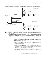
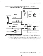
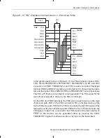
The bused EMU0/1 signals go into a programmable logic array device
PAL
R
whose function is to generate a low pulse on the EMU0/1-IN signal
when a low level is detected on the EMU0/1-OUT signal. This pulse must
be longer than one TCK period to affect the devices but less than 10
µ
s
to avoid possible conflicts or retriggering once the emulation software
clears the device’s pins.
-
During a RUNB debugger command or other external analysis count, the
EMU0/1 pins on the target device become totem-pole outputs. The EMU1
pin is a ripple carry-out of the internal counter. EMU0 becomes a
proces-
sor-halted signal. During a RUNB or other external analysis count, the
EMU0/1-IN signal to all boards must remain in the high (disabled) state.
You must provide some type of external input (XCNT_ENABLE) to the
PAL
R
to disable the PAL
R
from driving EMU0/1-IN to a low state.
-
If you use sources other than TI processors (such as logic analyzers) to
drive EMU0/1, their signal lines must be isolated by open-collector drivers
and be inactive during RUNB and other external analysis counts.
-
You must connect the EMU0/1-OUT signals to the emulation header or
directly to a test bus controller.
Figure E–12. Suggested Timings for the EMU0 and EMU1 Signals
EMU0/1-IN
EMU0/1-OUT
TCK


