Interrupts
5-26
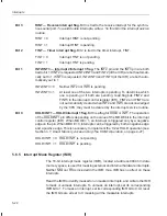
Figure 5–9 shows the ICR, and bit descriptions follow the figure.
Figure 5–9. ’C2xx Interrupt Control Register (ICR) — I/O-Space Address FFECh
15
5
4
3
2
1
0
ÉÉÉÉÉÉÉÉÉÉÉÉÉ
ÉÉÉÉÉÉÉÉÉÉÉÉÉ
Reserved
MODE
FINT3
FINT2
MINT3
MINT2
0
R/W–0
R/W1C–0
R/W1C–0
R/W–0
R/W–0
Note:
0 = Always read as zeros; R = Read access; W = Write access; W1C = Write 1 to this bit to clear it to 0;
value following dash (–) is value after reset.
Bits 15–5
Reserved. Bits 15–5 are reserved and are always read as 0s.
Bit 4
MODE — Pin mode. Bit 4 selects one of two possible modes for the HOLD/INT1 pin.
MODE = 0
Double-edge mode. The HOLD/INT1 pin is both negative- and positive-
edge sensitive. A falling edge or a rising edge triggers an interrupt re-
quest. This mode is necessary for proper implementation of a HOLD op-
eration.
MODE = 1
Single-edge mode. A falling edge (only) on the HOLD/INT1 pin triggers
an interrupt request.
Bit 3
FINT3 — Interrupt 3 flag. If MINT3 = 1, an interrupt request on the INT3 pin sets
FINT3 and bit 1 of the IFR (INT2/INT3).
FINT3 = 0
INT3 is not pending.
FINT3 = 1
INT3 is pending.
Bit 2
FINT2 — Interrupt 2 flag. If MINT2 = 1, an interrupt request on the INT2 pin sets
FINT2 and bit 1 of the IFR (INT2/INT3).
INT2 = 0
INT2 is not pending.
INT2 = 1
INT2 is pending.
Bit 1
MINT3 — Interrupt 3 mask. This bit masks the external interrupt INT3 or, in conjunc-
tion with the INT2/INT3 bit of the IMR, unmasks INT3.
MINT3 = 0
INT3 is masked. Neither FINT3 nor bit 1 of the IFR (INT2/INT3) is set
by a request on the INT3 pin.
MINT3 = 1
INT3 is unmasked. Flag bits FINT3 and INT2/INT3 are both set by a
request on the INT3 pin.


